Bicycle control device

a control device and bicycle technology, applied in mechanical control devices, bicycle brakes, instruments, etc., can solve the problems of difficult for the rider to grip the grip part, the grip part will not readily increase in size, so as to improve the ease of operation of the control lever member, the effect of improving the ease of initial adjustment and improving the grip par

Active Publication Date: 2014-06-26
SHIMANO INC
View PDF22 Cites 19 Cited by
  • Summary
  • Abstract
  • Description
  • Claims
  • Application Information

AI Technical Summary

Benefits of technology

[0046]In accordance with a thirty-eighth aspect, the bicycle control device according to the thirty-seventh aspect is configured so that the adjustment member has an adjustment screw for adjusting an effective length of the rod part. In this aspect, adjusting the length of the rod part allows for easy adjustment of the initial position of the piston.
[0047]In accordance with the present invention, the hydraulic fluid pressure generator is dispos...

Problems solved by technology

Thus, the grip part will not readily increase in size even if a hydraulic fluid pressure generator is disposed on the grip part.
Thus, when a rider attempts to generate hydraulic pressure of the volume and pressure necessary to cause the...

Method used


Image

  • Bicycle control device
  • Bicycle control device
  • Bicycle control device

Examples


first embodiment

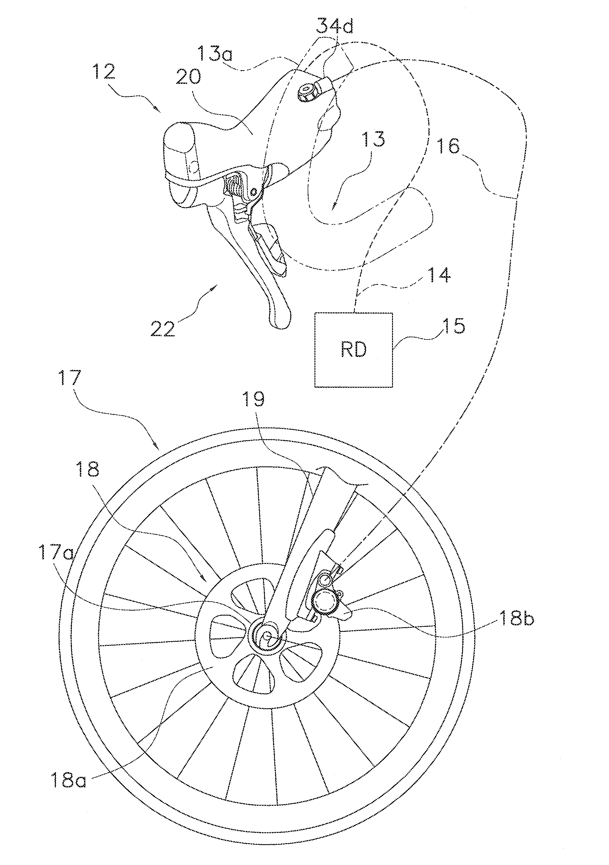
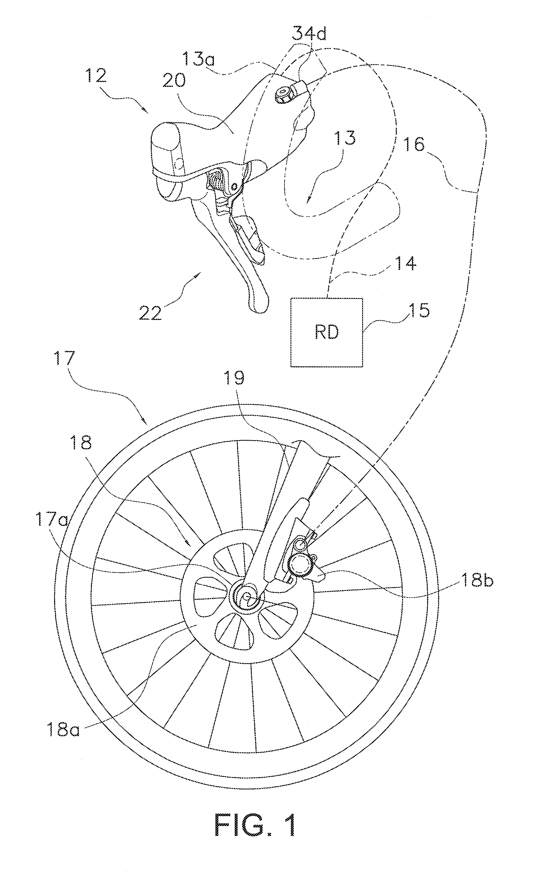
[0068]Referring initially to FIG. 1, a perspective view of a bicycle control device 12 that is mounted to a portion of a drop handlebar 13 according to a Here, only the bicycle control device 12 on the right side of the drop handlebar 13 is shown in FIG. 1. However, it will be apparent that the left side of the drop handlebar 13 has a similar bicycle control device that includes the features of the bicycle control device 12 as discussed herein.

[0069]A shift cable 14 acting as a control cable connects the right bicycle control device 12 to a rear derailleur 15. The shift cable 14 is a Bowden cable having an inner cable and an outer casing. A hydraulic fluid pressure hose 16 connects the right bicycle control device 12 to a braking device 18 for braking a front wheel 17. The braking device 18 is a hydraulic fluid pressure disc brake device which is actuated by hydraulic fluid pressure. The braking device 18 includes a brake disc 18a and a caliper 18b. The brake disc 18a is fixedly at...

first modification

[0110

[0111]In the following description, only those features differing from the embodiment described above are described and numbered in the drawings, and description of the configuration and operation of other features similar to those of the embodiment described above, as well as numbering thereof in the drawings, will be omitted.

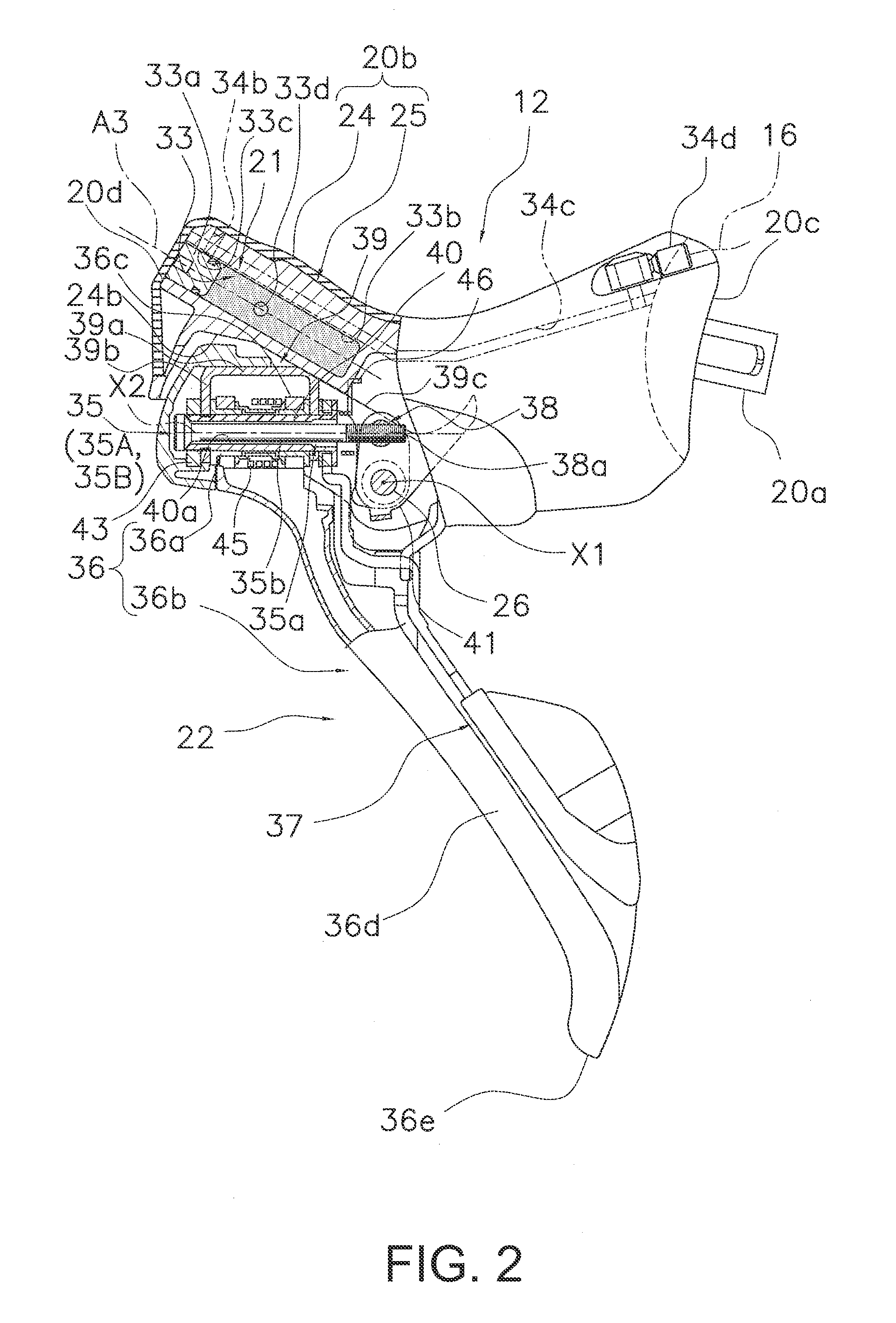
[0112]In the embodiment described above, the second axis X2 and the cable take-up axis A2 were coaxial, but the present invention is not limited to such a configuration. As shown in FIG. 11, the second axis X2 and the cable take-up axis A2 can be on different axes in a control device 112. In FIG. 11, the cable take-up axis A2 of a shift-operating mechanism 123 is disposed below the second axis X2 of a control lever member 122. The cable take-up axis A2 and the second axis X2 may also be disposed so as to intersect.

second modification

[0113

[0114]In the embodiment described above, the adjustment bolt 35b of the adjustment mechanism 35 (i.e., the piston-position-adjusting mechanism 35A and the control lever position adjustment mechanism 353B) is disposed penetrating the support shaft 40 along the second axis X2, but the present invention is not limited to such a configuration. In a control device 212 according to a second modification, as shown in FIG. 12, an adjustment bolt 235b (an example of a second adjustment bolt, a fourth adjustment bolt, or a sixth adjustment bolt) serving as an adjustment member 235a (an example of a second adjustment member or a fourth adjustment member) of an adjustment mechanism 235 (constituted by a piston-position-adjusting mechanism 235A and a control lever position adjustment mechanism 235B) is disposed near a lever shaft 26 having a first axis X1. The adjustment bolt 235b is screwed into a screw hole 236g formed in the lever 36b, and an end thereof contacts a coupling part 241b of ...


PUM


Abstract

A bicycle control device includes a housing member, a control lever member, a shift-operating mechanism and a hydraulic fluid pressure generator. The housing member has an attachment part for attachment to a handlebar, and a grip part extending longitudinally between first and second ends of the grip part. The attachment part is provided on the first end of the grip part. The attachment part is provided on the first end of the grip part. The control lever member is pivotally provided with respect to the housing member. The shift-operating mechanism is supported by the housing member. The shift-operating mechanism includes a control cable attachment part that is configured to be coupled to a shifting device by a control cable. The hydraulic fluid pressure generator has a cylinder provided in the grip part of the housing member, and a piston movably disposed within the cylinder by movement of the control lever member to generate fluid pressure for controlling a braking device. The cylinder is disposed closer to the second end of the grip part than the shift-operating mechanism.

Description

CROSS-REFERENCE TO RELATED APPLICATIONS[0001]This application claims priority under 35 U.S.C. §119 to Japanese Patent Application No. 2012-007804, filed Dec. 26, 2012. The entire disclosure of Japanese Patent Application No. 2012-007804 is hereby incorporated herein by reference.BACKGROUND[0002]1. Field of the Invention[0003]This invention generally relates to a bicycle control device. More specifically, the present invention relates to a bicycle control device which can be mounted on the handlebar of a bicycle and which can control a braking device and a shifting device.[0004]2. Background Information[0005]Bicycle control devices are conventionally known, which can be mounted on a handlebar of a bicycle for controlling both a braking device and a shifting device (for example, Japanese Unexamined Patent Application Publication No. 2004-039507). A conventional bicycle control device is provided with a housing member having an attachment part capable of being attached to a handlebar a...

Claims


Application Information

Patent Timeline
IPC IPC(8): B62L3/02
CPCB60T7/102B62L3/023B60T11/16G05G1/04B60T11/18Y10T74/20287B62K23/06B62M25/04
Inventor WATARAI, ETSUYOSHIKARIYAMA, OSAMUMATSUSHITA, TATSUYANAKAKURA, MASAHIRO
Owner SHIMANO INC
Why Eureka
Try Eureka