

Lock core assembly
- Summary
- Abstract
- Description
- Claims
- Application Information
AI Technical Summary
Benefits of technology
Problems solved by technology
Method used
Image

Examples
Embodiment Construction
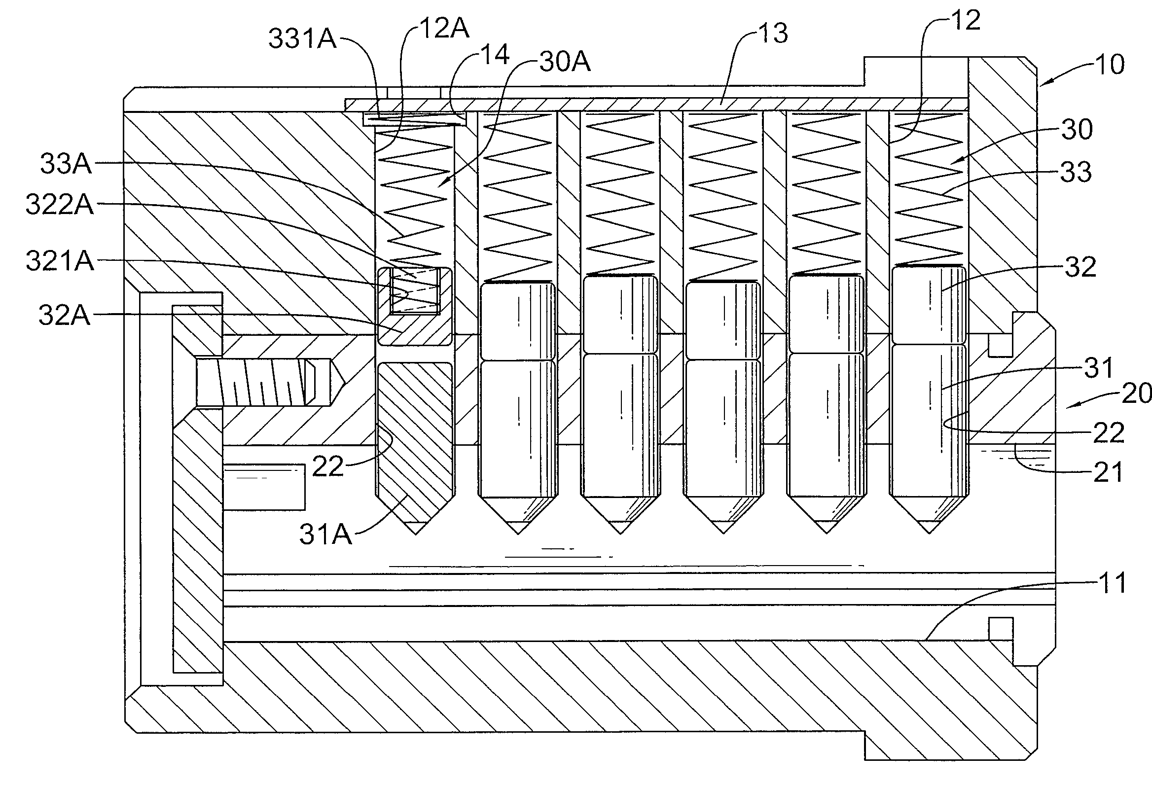
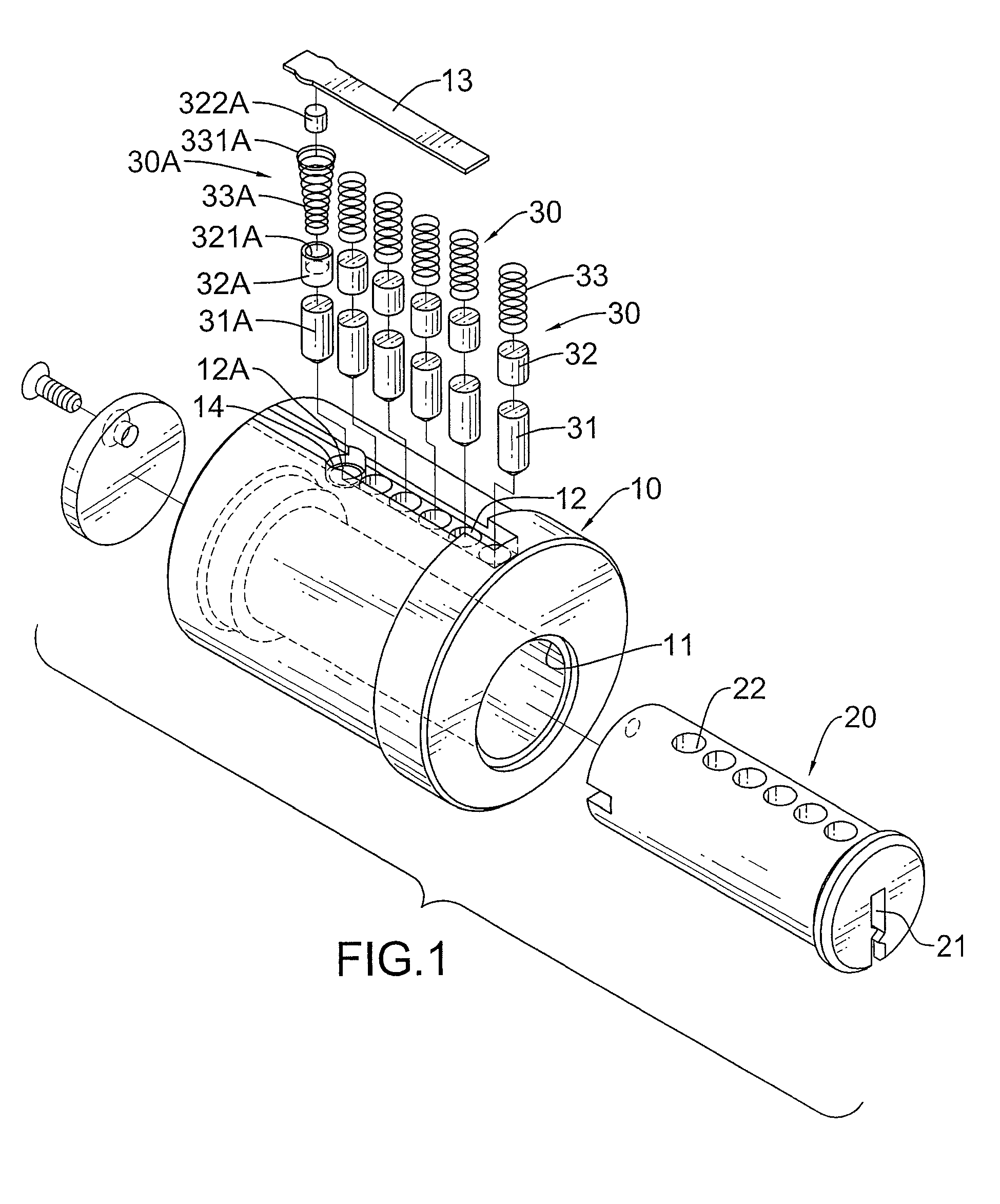
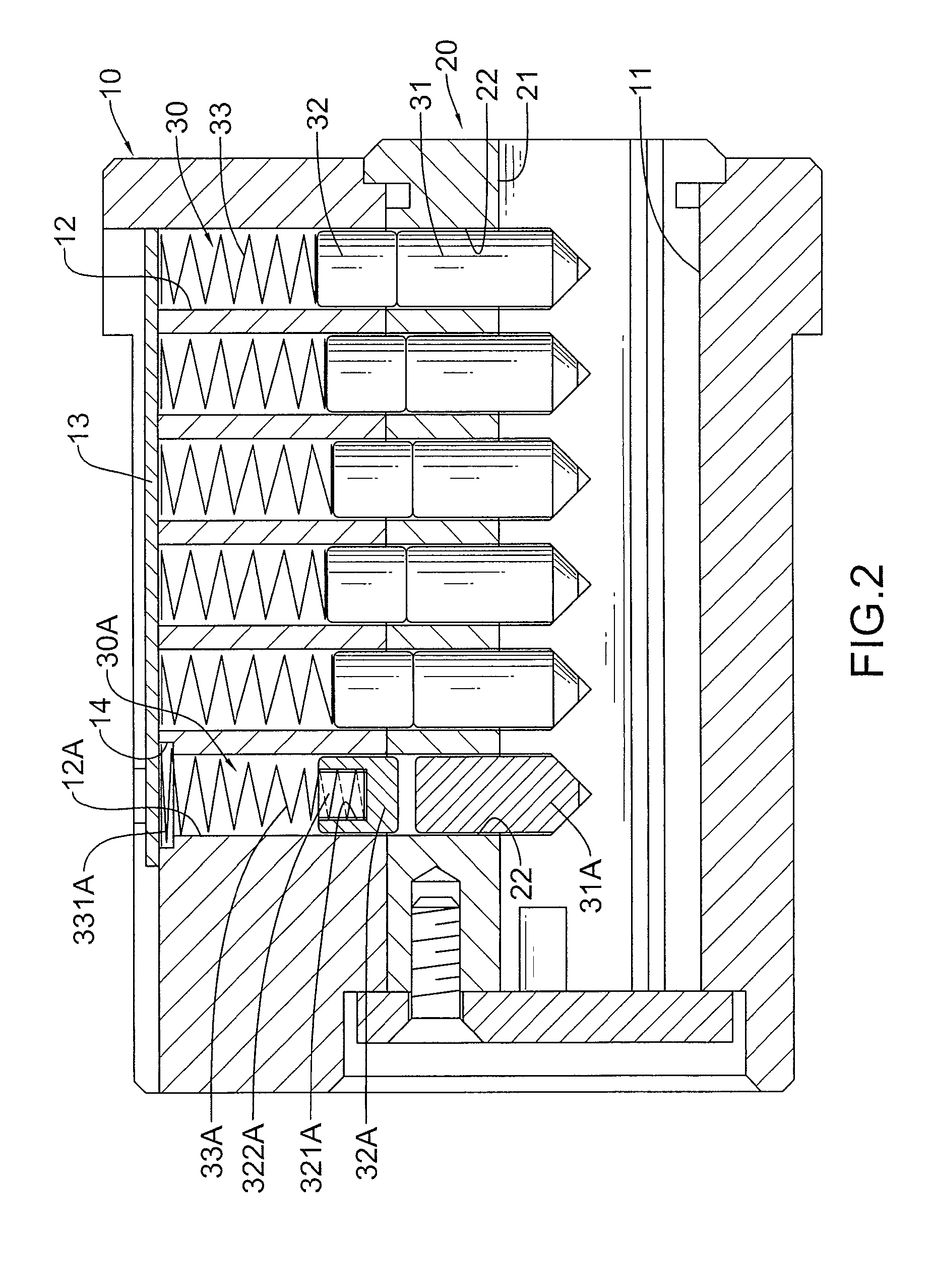
[0014]With reference to FIGS. 1 and 2, a lock core assembly in accordance with the present invention has a lock shell (10), a lock core (20) and a pin segment.
[0015]The lock shell (10) has an outer surface, a core mount (11), multiple upper pin chambers (12, 12A), at least one retaining cavity (14) and a lid (13).
[0016]The core mount (11) is formed longitudinally through the lock shell (10) and has an inner surface.
[0017]The upper pin chambers (12, 12A) are formed radially through the outer surface of the lock shell (10), are aligned longitudinally, communicate with the core mount (11).
[0018]The at least one retaining cavity (14) is formed in the outer surface of the lock shell (10), formed around, communicates with and is larger than at least one of the upper pin chambers (12A).
[0019]The lid (13) is mounted detachably on the outer surface of the lock shell (10) and covers the upper pin chambers (12, 12A).
[0020]The lock core (20) may be a cylinder, is mounted rotatably in the core m...
PUM
 Abstract
Description
Claims
Application Information