Cross-quad and vertically coupled inertial sensors

a cross-quad and vertically coupled, sensor technology, applied in the field of sensors, can solve the problems of imbalance in forces transverse to longitudinal drive fingers, adverse effects of rotational vibration noise on the drive frequency ofinertial sensors,

Active Publication Date: 2008-09-09
ANALOG DEVICES INC
View PDF117 Cites 88 Cited by
  • Summary
  • Abstract
  • Description
  • Claims
  • Application Information

AI Technical Summary

Benefits of technology

[0009]In certain embodiments, the first and second frames are interconnected by a first horizontal coupling that enables anti-phase movements of the frames along their respective axes but substantially prevents in-phase movements of the frames, while the third and fourth frames are interconnected by a second horizontal coupling that enables anti-phase movements of the frames along their respective axes but substantially prevents in-phase movements of the frames.
[0021]The vertical coupling may include a first pair of interconnected levers coupled to one of the frames, the first pair of levers including a first lever and a second lever; a second pair of interconnected levers coupled to the other of the frames, the second pair of levers including a third lever and a fourth lever; a plurality of lever support structures allowing the levers to pivot as the frames move in anti-phase to one another; a first coupling flexure interconnecting the first lever and the third lever substantially at their respective pivot points; and a second coupling flexure interconnecting the second lever and the fourth lever substantially at their respective pivot points. The coupling flexures substantially prevent in-phase movements of the frames.

Problems solved by technology

Inertial sensors, such as MEMS gyroscopes, often are adversely affected by rotational vibration noise at the drive frequency (often referred to as “wobble”).
In particular, MEMS gyroscopes can produce false readings if they are not capable of distinguishing between rotational vibration and the actual movement they are intended to detect.
Also, distortion of the geometry of a MEMS device having an oscillating mass, such as a gyroscope, can produce an imbalance in the forces transverse to a longitudinal drive finger.
This imbalance can cause a net force that is indistinguishable from a Coriolis force.
Consequently, a gyroscope can produce false outputs.

Method used


Image

  • Cross-quad and vertically coupled inertial sensors
  • Cross-quad and vertically coupled inertial sensors
  • Cross-quad and vertically coupled inertial sensors

Examples


Embodiment Construction

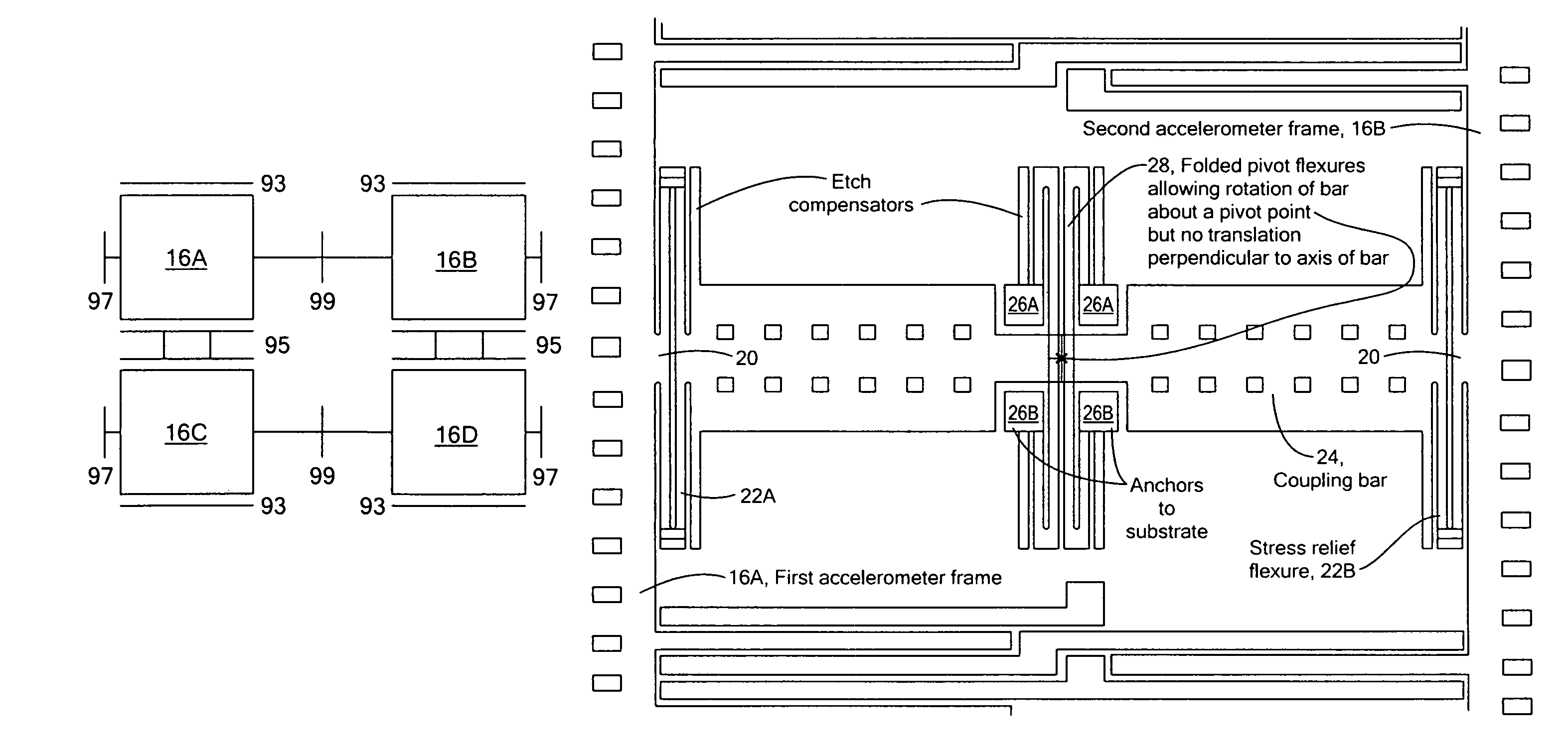
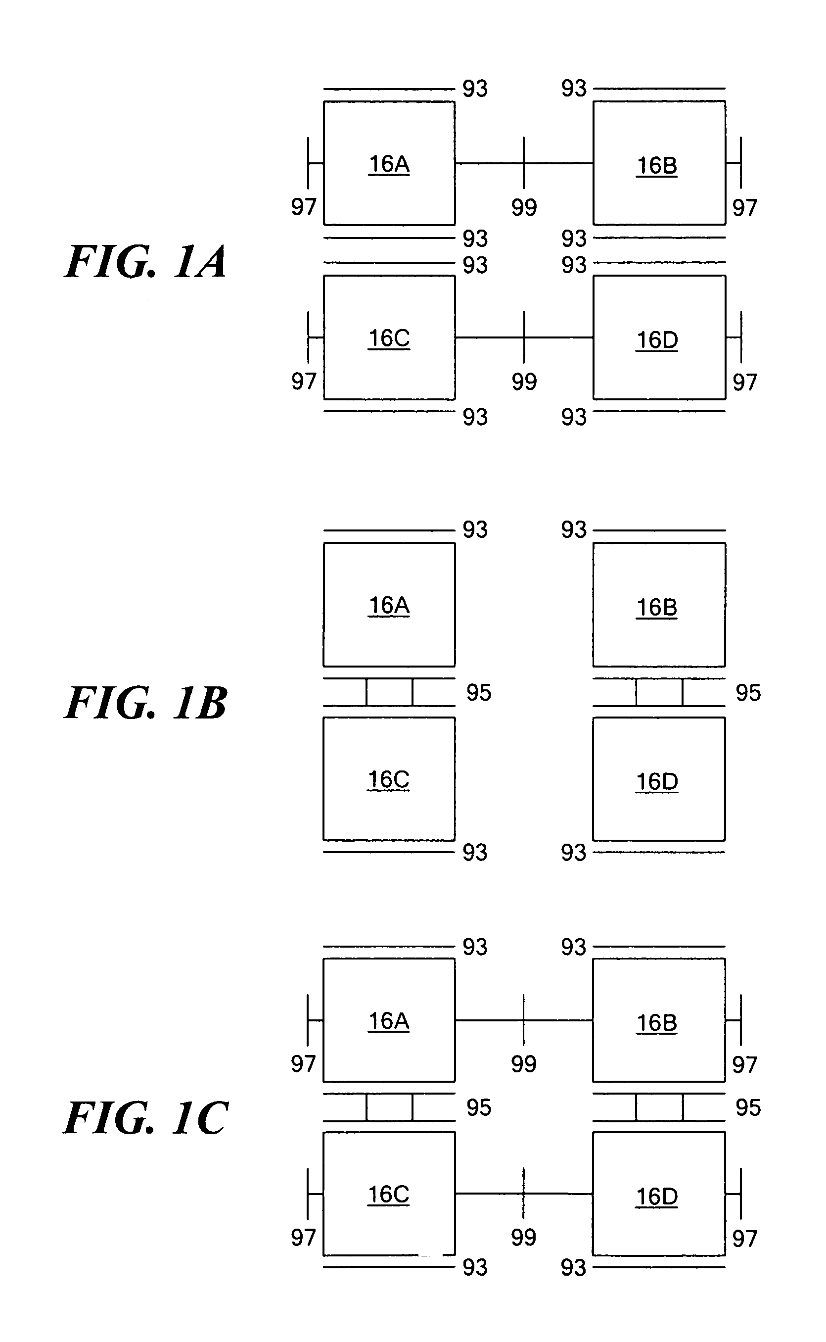
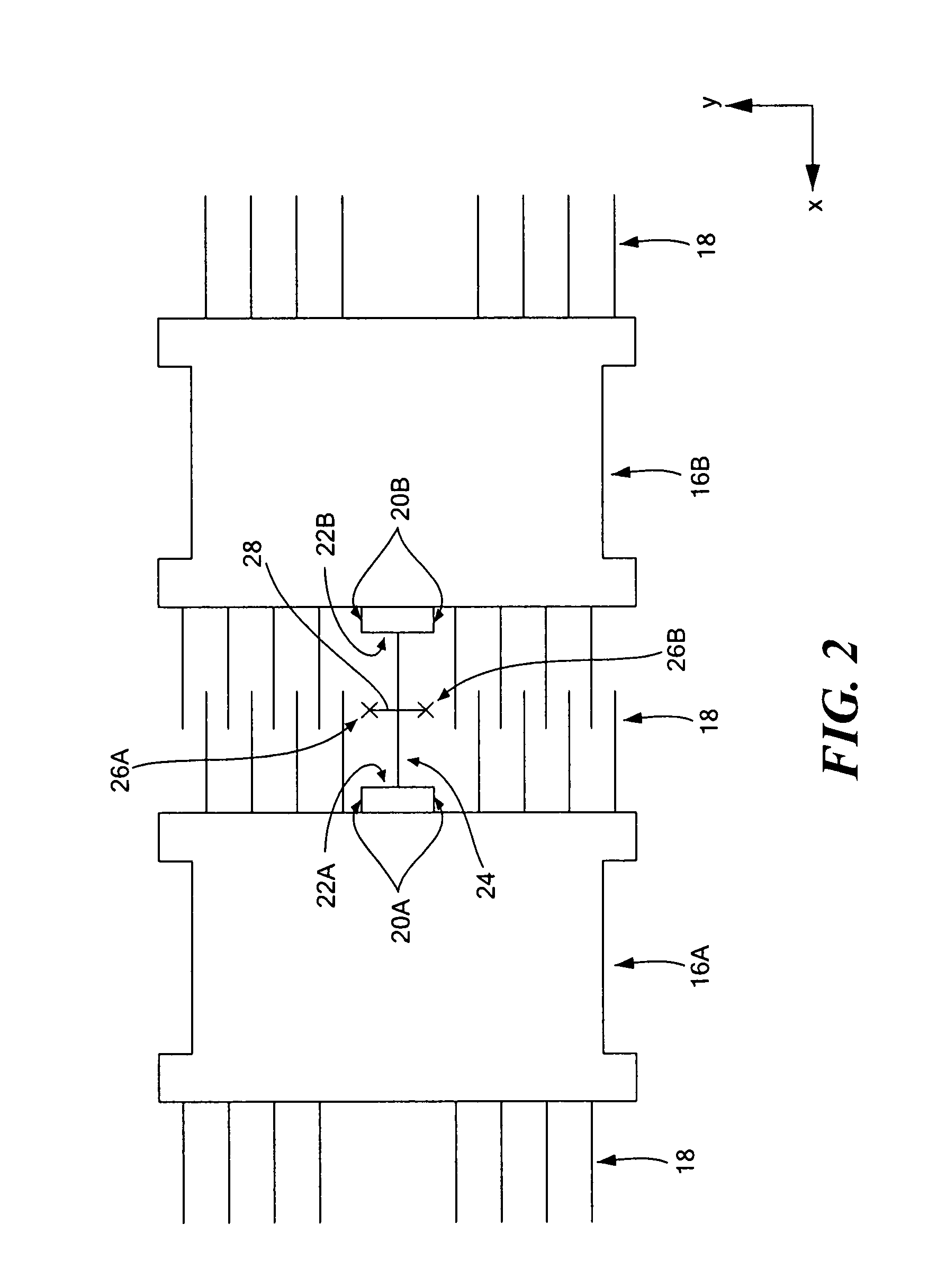
[0042]In certain embodiments of the present invention, an inertial sensor includes four sensor elements that are arranged in a “cross-quad” configuration. In preferred embodiments, the sensor elements are microelectromechanical systems (i.e., “MEMS”) gyroscopes. The sensor elements together combine to effectively perform the function of a single gyroscope. The sensor elements are typically suspended above one or more underlying substrates (not shown) and are secured at various points to the substrate(s). Desirability of using a cross-quad arrangement of gyroscopes is discussed in U.S. Pat. No. 6,122,961, the disclosure of which is incorporated herein, in its entirety, by reference.

[0043]Each gyroscope has at least one resonator (mass) suspended within a frame. For the sake of discussion, the resonators of the inertial sensor gyroscopes are configured to move along two parallel X axes, while the frames of the inertial sensor gyroscopes are configured to move along two parallel Y axes...


PUM


Abstract

An inertial sensor includes a cross-quad configuration of four interconnected sensor elements. Each sensor element has a frame and a resonator suspended within the frame. The sensor elements are arranged so that the frames of adjacent sensor elements are allowed to move in anti-phase to one another but are substantially prevented from moving in phase with one another. The sensor elements may be configured in a horizontally coupled arrangement, a vertically coupled arrangement, or a fully coupled arrangement. A pair of sensor elements may be vertically coupled.

Description

CROSS-REFERENCE TO RELATED APPLICATION[0001]The present invention is related to U.S. Provisional Patent Application No. 60 / 561,931 entitled Inertial Sensor Array and Coupling apparatus for the Same, filed on Apr. 14, 2004 in the names of John A. Geen, William A. Clark, and Jinbo Kuang, which is hereby incorporated herein by reference in its entirety.FIELD OF THE INVENTION[0002]The invention generally relates to sensors and, more particularly, the invention relates to inertial sensors.BACKGROUND OF THE INVENTION[0003]Inertial sensors, such as MEMS gyroscopes, often are adversely affected by rotational vibration noise at the drive frequency (often referred to as “wobble”). In particular, MEMS gyroscopes can produce false readings if they are not capable of distinguishing between rotational vibration and the actual movement they are intended to detect.[0004]Also, distortion of the geometry of a MEMS device having an oscillating mass, such as a gyroscope, can produce an imbalance in the...

Claims


Application Information

Patent Timeline
Patent Type & Authority Patents(United States)
IPC IPC(8): G01P9/04
CPCG01C19/574G01C19/56
Inventor GEEN, JOHN A.KUANG, JINBO
Owner ANALOG DEVICES INC
Why Eureka
Try Eureka