Wide angle arrowhead

a wide angle, arrowhead technology, applied in the field of archery, can solve the problems of reducing the aerodynamic qualities of the arrowhead, unwittingly creating drag far more detrimental to flight, and adding weight to the arrow, so as to achieve the effect of minimal structure and surface area, and light weigh

Inactive Publication Date: 2008-09-09
BEAR ARCHERY
View PDF20 Cites 20 Cited by
  • Summary
  • Abstract
  • Description
  • Claims
  • Application Information

AI Technical Summary

Benefits of technology

[0008]According to one embodiment of the present invention, there is provided a wide angle arrowhead including suitable structure for mounting of a plurality of blades to a mounting fixture and suitable structure for mounting of the wide angle arrowhead to the forward portion of an arrow. The mounting fixture is a one-piece construction and includes a chisel point and a rearward facing circular recess for capture of the forward portion of one or more cutting blades, a first shaft portion extending from the circular recess against which the base edge at the lower portion of each blade aligns, an annular and slotted beveled ring juxtaposing the first shaft portion, the slots of which accommodate the base edges at the lower portions of the arrow blades, a second and larger slotted shaft portion, the slots of which are extensions of the slots in the annular and slotted beveled ring and which also accommodate the base edges at the lower portions of the arrow blades and a threaded shaft portion extending from the larger slotted shaft portion which is utilized to mount the mounting fixture and arrow blades, i.e., the entire wide angle arrowhead, to the arrow shaft. Each blade includes a blade capture protrusion at the rearwardly located trailing edge which is captured by a mounting ferrule. The blades are formed to have minimum structure and reduced drag surfaces and to have a low ratio of blade cutting edge length to blade trailing edge length where the interior angle between the blade cutting edge of the blades is at a relatively wide angle with respect to the center line or longitudinal axis of the arrow shaft. Where many common arrowhead blades have a relationship where the interior angle of the blade cutting edge to the arrow shaft centerline angle is in the range of 10° to slightly less than 45°, the present invention has a blade cutting edge to arrow shaft centerline interior wide angle which can range from an interior wide angle of 45° to an interior wide angle of 75°. Also, drag is minimized by the utilization of a thin ground leading blade cutting edge, an additional benefit of which is the decreasing of the cutting edge bluntness, thereby enhancing easy target penetration.
[0010]Another significant aspect and feature of the present invention is an arrowhead which contributes to and improves flight characteristics of an arrow.
[0012]Still another significant aspect and feature of the present invention is a wide angle arrowhead having minimal drag.

Problems solved by technology

Often, the structure of an arrowhead is such that complex surfaces and devices composing the arrowhead are included, thereby not only adding weight to the arrow but also diminishing aerodynamic qualities of the arrowhead due to a multiplicity of drag causing surfaces.
Such drag causing surfaces can be cutouts which beneficially lighten the weight of the arrow but which unwittingly create drag far more detrimental to flight than the benefit to flight derived by weight reduction.
Of course, increased drag and increased weight are detrimental to suitable flight characteristics of an arrow, especially with respect to distance.
Such an elongated arrowhead may also be of such weight as to be detrimental to the length of flight and trajectory of the arrow.

Method used


Image

  • Wide angle arrowhead
  • Wide angle arrowhead
  • Wide angle arrowhead

Examples


Embodiment Construction

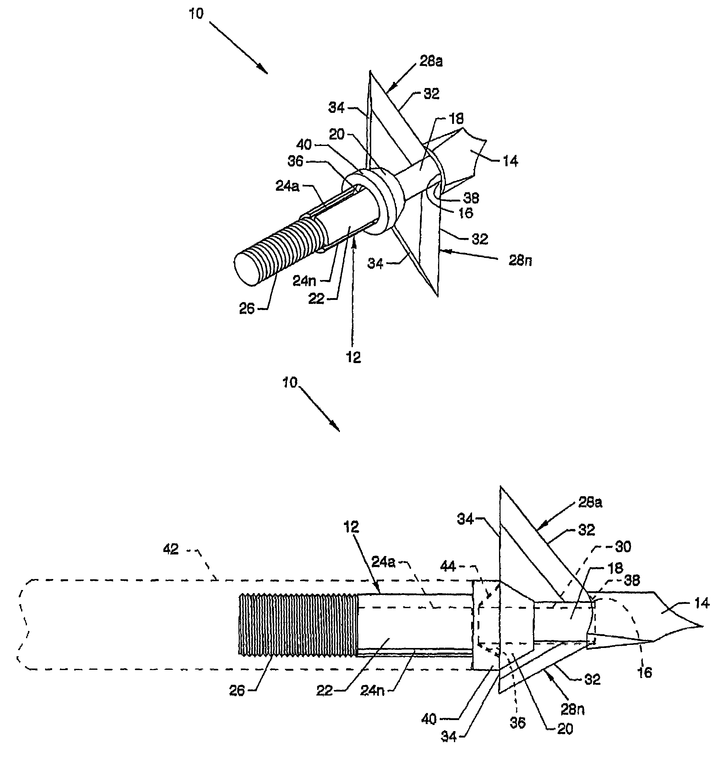
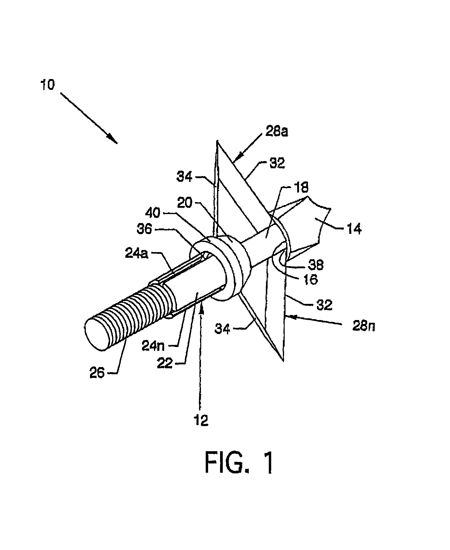
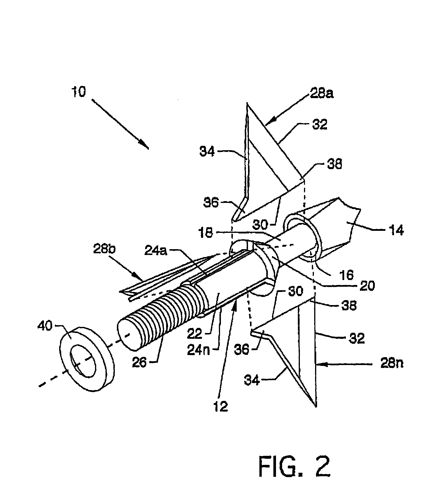
[0024]FIG. 1 is an isometric view of a wide angle arrowhead 10, the present invention, and FIG. 2 is an exploded isometric view of the wide angle arrowhead 10. For purposes of example and illustration, the wide angle arrowhead 10 includes three blades, although different numbers of blades could be incorporated. With reference to FIGS. 1 and 2, the invention is now described starting generally at the forward portion of a mounting fixture 12. The mounting fixture 12, preferably a one-piece structure, forms the wide angle arrowhead 10 in part and accommodates other components comprising the instant invention. A chisel point 14 is located at the forward region of the mounting fixture 12. An angled rearwardly facing circular recess 16 is located at the junction of the rearward facing portion of the chisel point 14 and a first shaft portion 18 which is smooth and uninterrupted. A beveled ring 20, which is annular and which is slotted, is located adjacent to the first shaft portion 18 betw...


PUM


Abstract

A wide angle arrowhead which is light weight, and which has minimal structure and surface area to decreased arrowhead weight, surface area and drag to increase performance of an arrow to which it is attached. A blade cutting edge of the wide angle arrowhead maintains an interior angle relationship to the centerline of an arrow shaft where such relationship can be fashioned to have one interior angular relationship within a specified angular range. Also, drag is minimized by the utilization of a thin ground blade cutting edge, an additional benefit of which is the decreasing of the cutting edge bluntness, thereby enhancing easy target penetration.

Description

CROSS REFERENCES TO RELATED APPLICATIONS[0001]This application is a continuation application of application Ser. No. 10 / 603,755 filed on Jun. 25, 2003 now U.S. Pat. No. 6,866,600, which is incorporated herein by reference.BACKGROUND OF THE INVENTION[0002]1. Field of the Invention[0003]The present invention relates to the field of archery, and more particularly, relates to an arrowhead having a wide angle.[0004]2. Description of the Prior Art[0005]Archers have long sought out an arrow which would outperform other arrows. Performance of an arrow is influenced by weight, component surface area, surfaces having parasitic drag, stabilization techniques, structure and other such considerations. One area of constant consideration and change is the arrowhead which is located at the front portion of an arrow. Often, the structure of an arrowhead is such that complex surfaces and devices composing the arrowhead are included, thereby not only adding weight to the arrow but also diminishing aer...

Claims


Application Information

Patent Timeline
Patent Type & Authority Patents(United States)
IPC IPC(8): F42B6/08
CPCF42B6/08
Inventor JOHNSON, GREGORY G.
Owner BEAR ARCHERY
Why Eureka
Try Eureka