Discharge device and discharge method for liquid material containing solid particles, and coating device

Active Publication Date: 2018-08-02
MUSASHI ENG INC
View PDF9 Cites 2 Cited by
  • Summary
  • Abstract
  • Description
  • Claims
  • Application Information

AI Technical Summary

Benefits of technology

The invention allows for liquid materials containing solid particles to be discharged with the solid particles dispersed throughout the liquid with minimal additional stirring. This is possible because the stirring is done by reversing the flow of the liquid material in the same flow passage, which helps to minimize deposition of the solid particles in the passage.

Problems solved by technology

In trying to discharge, among various types of liquid materials to be discharged by the dispenser, particularly a liquid mixed with solid particles having a greater specific gravity than the liquid, a problem arises in that the solid particles deposit at the bottom of a container and in a recess of a flow passage with the lapse of time.
Furthermore, if dispersion of the solid particles is insufficient, a trouble of causing a discharge failure with clogging of the nozzle may occur.
However, even when the stirrer is disposed in association with the container, it may often occur that the solid particles deposit in a tubing connecting the container and a discharge mechanism, and that the liquid cannot be discharged in a state of the solid particles being dispersed in the liquid.

Method used


Image

  • Discharge device and discharge method for liquid material containing solid particles, and coating device
  • Discharge device and discharge method for liquid material containing solid particles, and coating device
  • Discharge device and discharge method for liquid material containing solid particles, and coating device

Examples


example

[A] Discharge Device

(A1) Configuration

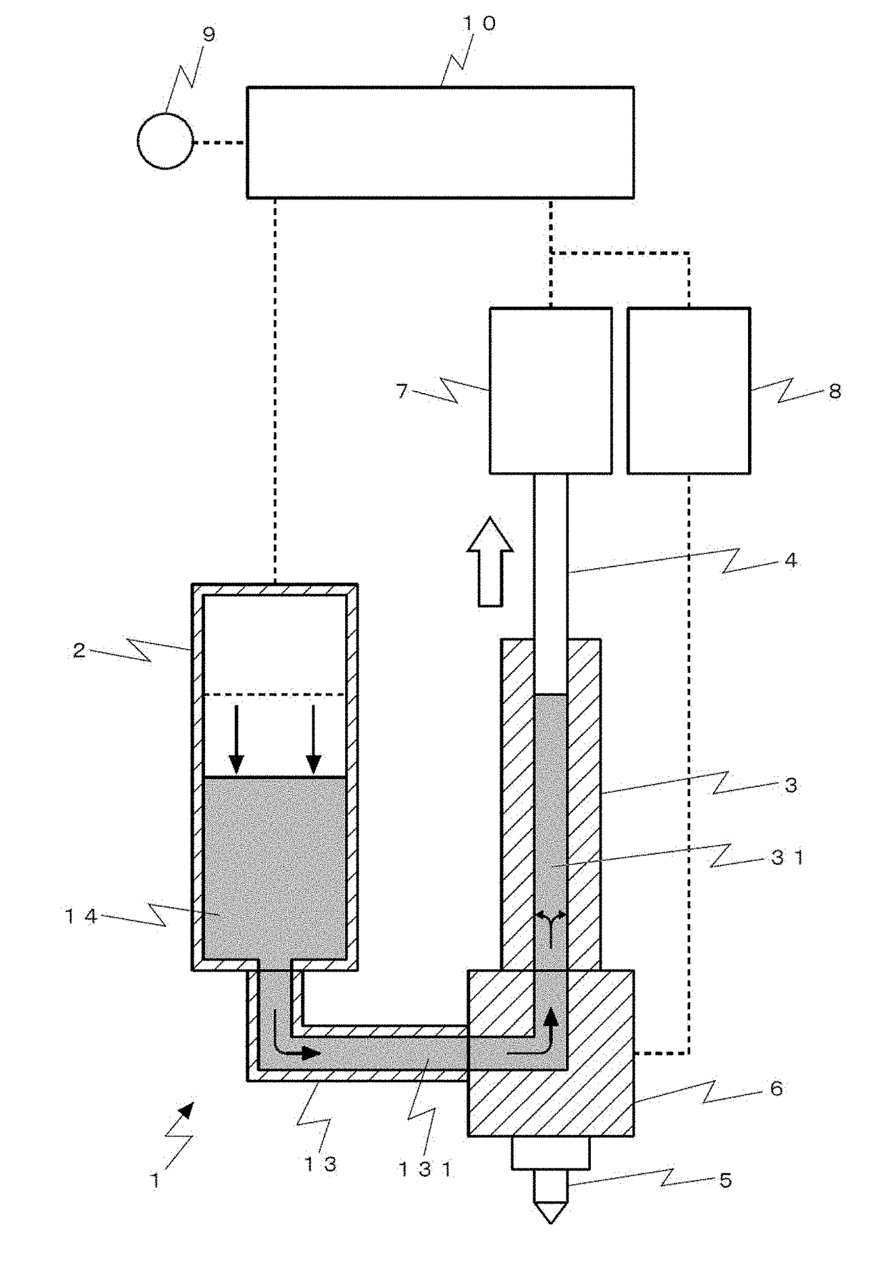
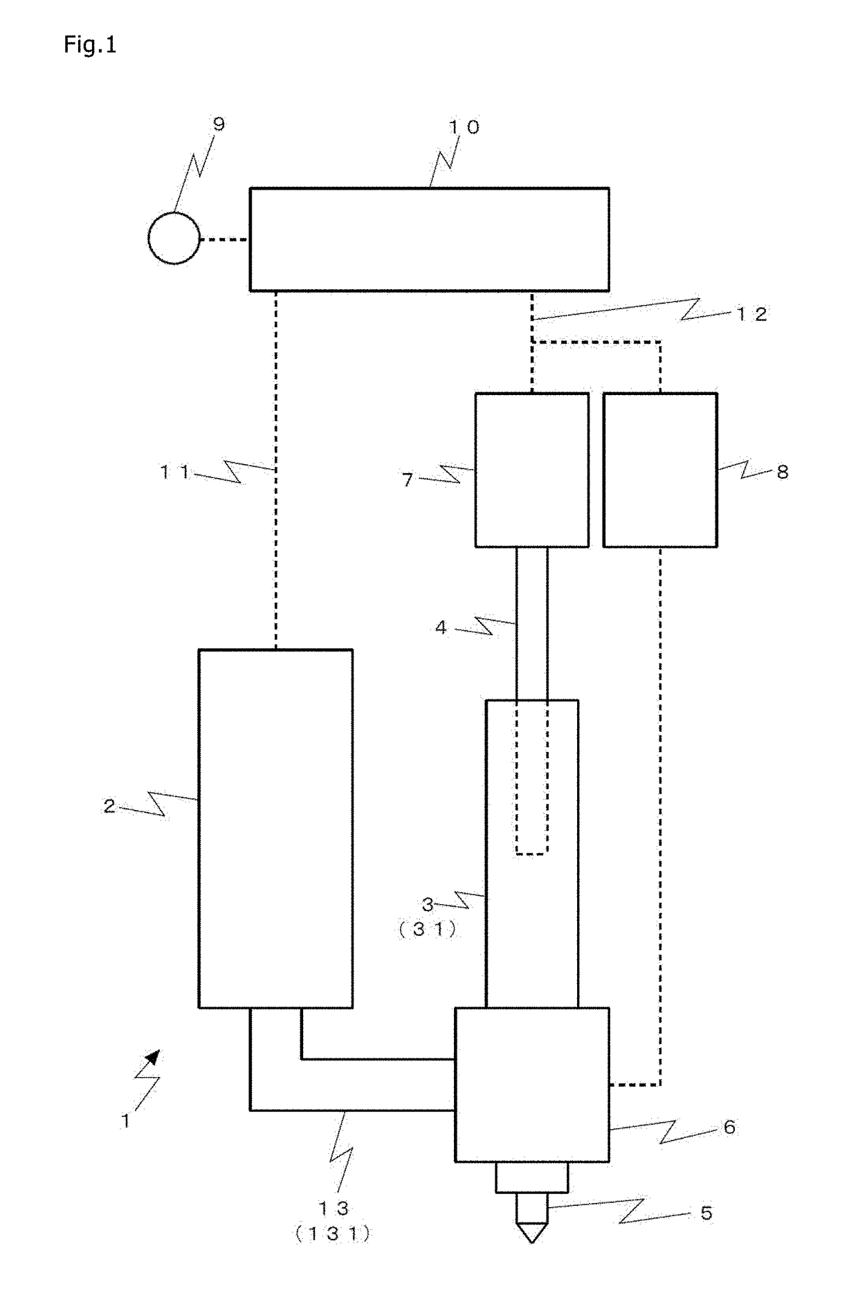
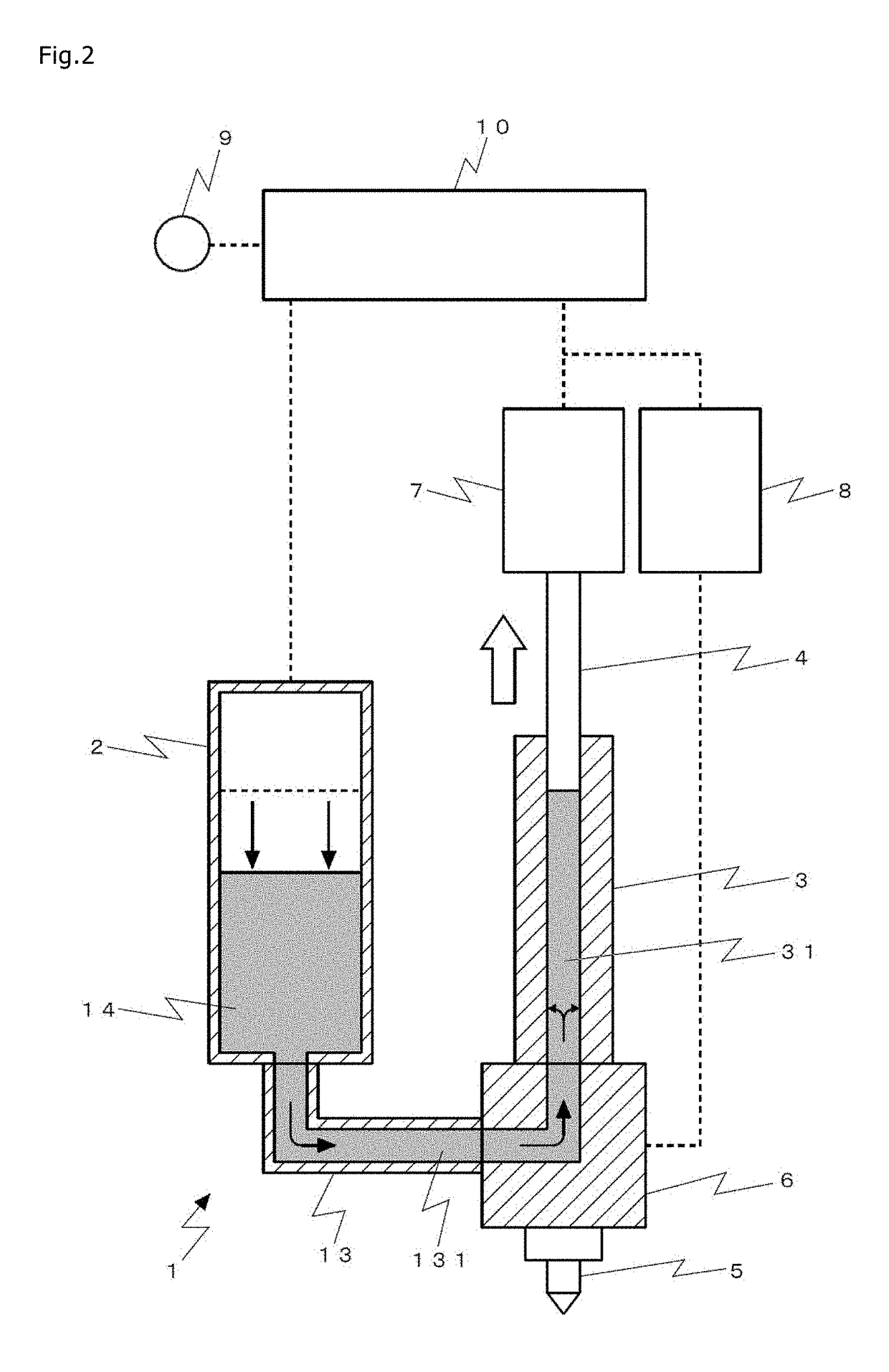
[0062]FIG. 5 is a side sectional view of principal part of a discharge device 1 according to Example. In FIG. 5, (a) represents the case where a selector valve 6 is at a first position at which a storage container 2 and a measuring unit 3 are communicated with each other, and (b) represents the case where the selector valve 6 is at a second position at which the measuring unit 3 and a nozzle 5 are communicated with each other. It is to be noted that, in FIG. 5, a hatched region represents a section.

[0063]The discharge device 1 according to Example of the present invention includes, as in the above-described embodiment, the storage container 2 in which a liquid material 14 is stored, the measuring unit 3 into which the liquid material 14 is filled, a plunger 4 that is moved forward and backward in the measuring unit 3, a nozzle 5 having a discharge port through which the liquid material 14 is discharged, the selector valve 6 that selectively esta...


PUM


Abstract

A device and a method of discharging a liquid in a state of solid particles being dispersed in the liquid with a minimum additional structure for dispersing the solid particles. A discharge device and an application device each include a storage container; a measuring unit having a measuring hole; a plunger disposed in the measuring hole; a nozzle; a selector valve having a first position at which the storage container and the measuring unit are communicated, and a second position at which the measuring unit and the nozzle are communicated; a plunger drive device; a selector valve drive device; and a discharge control device, wherein a discharge control program includes a filling stepinto the measuring hole; an ejection step; an inflow step causing the liquid material in the measuring hole to flow into the storage container; a discharge step; and a stirring step.

Description

TECHNICAL FIELD[0001]The present invention relates to a device and a method of applying a liquid material, which contains solid particles, in a state of the solid particles being dispersed in the liquid material.BACKGROUND ART[0002]As a device of distributing various types of liquid materials in units of a predetermined amount, there is known a “dispenser” including a container in which the liquid material is stored, and discharging the liquid material in units of the predetermined amount from a nozzle, which is connected to the container, by the action of a gas pressure or a mechanical pressure. For example, Patent Document 1 discloses a dispenser, proposed by the applicant, in which the liquid material is filled in a measuring hole to be discharged by moving backward a plunger held in slide contact with an inner wall of the measuring hole, and the liquid material is discharged from a nozzle by moving the plunger forward.[0003]In trying to discharge, among various types of liquid m...

Claims


Application Information

Patent Timeline
IPC IPC(8): B05C11/10H01L33/50B05D1/26B05D7/24
CPCB05C11/10H01L33/50B05D1/26B05D7/24B05C5/0233B05C17/00573B05C5/0216B05C5/0225B05C11/1034B01F31/651B05C11/1002B05C11/11B05C13/02C09D5/22
Inventor IKUSHIMA, KAZUMASA
Owner MUSASHI ENG INC
Why Eureka
Try Eureka