Medical equipment mounting system for an I.V. pole

a technology of medical equipment and mounting system, which is applied in the field of can solve the problems of not including a medical equipment mounting system, and achieve the effect of improving the safety and safety of patients

Active Publication Date: 2022-09-13
SHROPSHIRE CAMILLE
View PDF13 Cites 0 Cited by
  • Summary
  • Abstract
  • Description
  • Claims
  • Application Information

AI Technical Summary

Benefits of technology

[0005]It is one of the objects of the present invention to provide a medical mounting system for an I

Problems solved by technology

None of them, however, include a medical equipment mounting system for an I.V. pole

Method used


Image

  • Medical equipment mounting system for an I.V. pole
  • Medical equipment mounting system for an I.V. pole
  • Medical equipment mounting system for an I.V. pole

Examples


Embodiment Construction

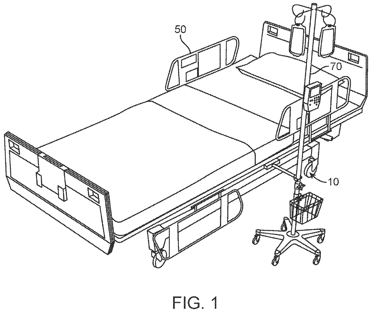
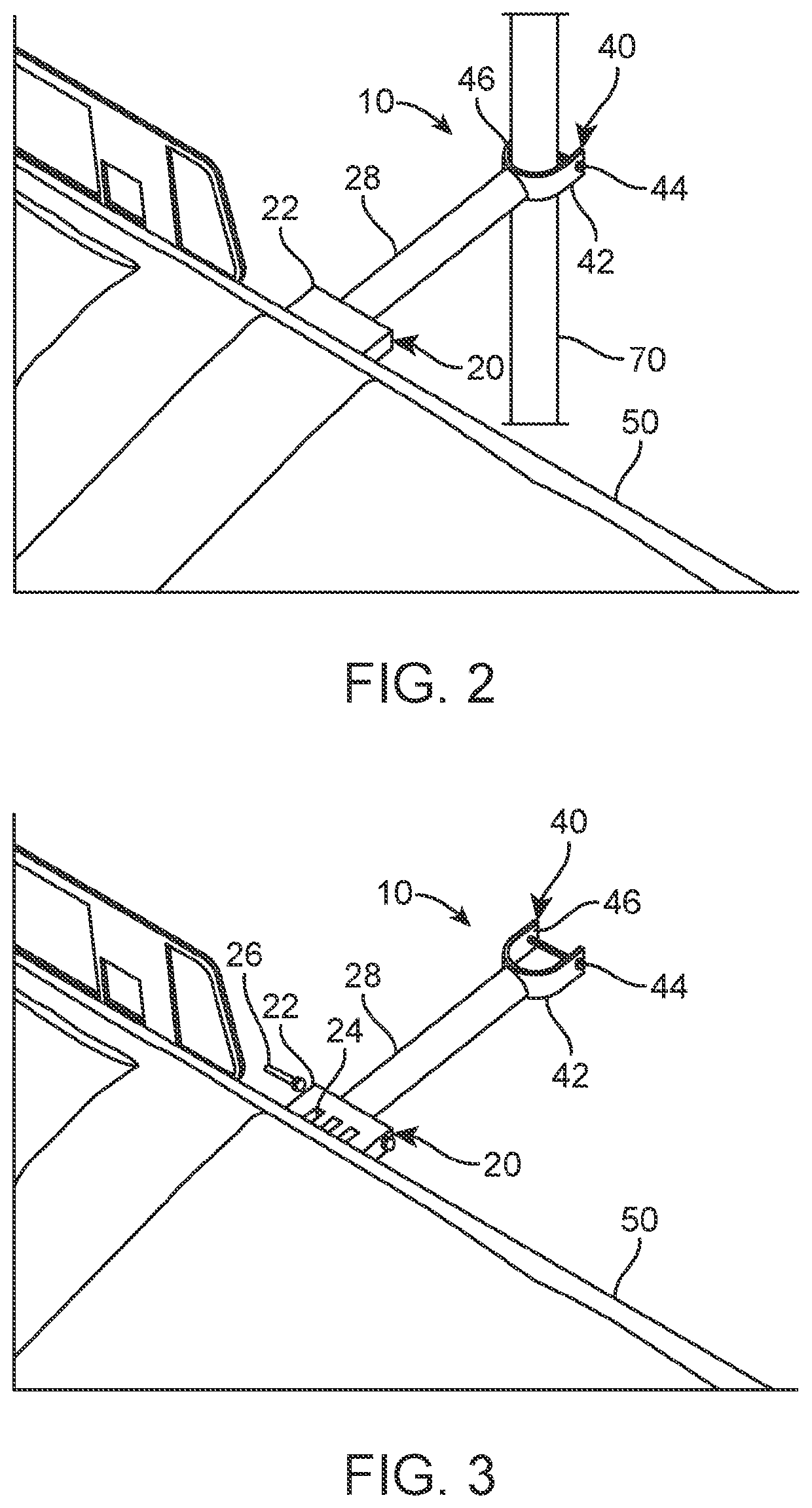
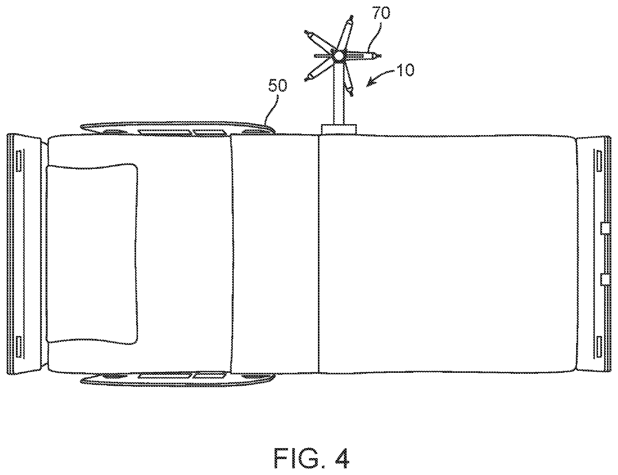
[0015]Referring now to the drawings, where the present invention is generally referred to with numeral 10, it can be observed a medical mounting system 10 which basically includes an arm assembly 20 and a clamp assembly 40.

[0016]Arm assembly 20 includes an arm plate 22 which is adapted to be attached to a patient bed frame 50. In on embodiment, patient bed frame 50 is a frame portion of a hospital patient bed in a hospital environment. It should be understood that any variation of a hospital patient bed may be used for the present invention. In the present implementation, arm plate 22 is a substantially cuboid structure with a rectangular shape. The arm plate may include four perimeter sidewalls and a top and bottom face. In the embodiment depicted in FIG. 2, arm plate 22 is welded directly onto the patient bed frame 50. As observed in the figure, arm plate 22 may be welded directly onto a top edge of the bade frame 50. Other embodiments may feature the arm plate 22 being secured to...


PUM


Abstract

A medical equipment mounting system for an I.V. pole including an arm having an adjustable clamp on the distal end, and a mounting plate. The mounting plate is welded to the side of a hospital bed. Furthermore, the proximal end of the arm is attached to the mounting plate. In one embodiment, the clamp is a U-shaped clamp having a security screw disposed along its opening. The security screw allows for the I.V. pole to be safely secured to the clamp and prevents the detachment of pole when a hospital patient bed is being transported or maneuvered.

Description

BACKGROUND OF THE INVENTION1. Field of the Invention[0001]The present invention relates to medical equipment mounting system and, more particularly, to a medical equipment mounting system for an I.V. pole that includes an arm having an adjustable clamp on a distal end which receives an I.V. to ease the simultaneous transportation of the I.V. pole and a hospital patient bed.2. Description of the Related Art[0002]Several designs for a medical mounting system have been designed in the past. None of them, however, include a medical equipment mounting system for an I.V. pole including an arm having an adjustable clamp on the distal end, and a mounting plate. The mounting plate is welded to the side of a hospital bed. Furthermore, the proximal end of the arm is attached to the mounting plate. In one embodiment, the clamp is a U-shaped clamp having a security screw disposed along its opening. The security screw allows for the I.V. pole to be safely secured to the clamp and prevents the det...

Claims


Application Information

Patent Timeline
IPC IPC(8): A61M5/14A61G7/05
CPCA61M5/1415A61G7/0503A61M2209/082A61G7/05A61G2203/80
Inventor SHROPSHIRE, CAMILLE
Owner SHROPSHIRE CAMILLE
Why Eureka
Try Eureka