Magnetic recording head with resistive heating element and thermal barrier layer

a technology of resistive heating element and magnetic recording head, which is applied in the field of magnetic recording, can solve the problems of deformation of the slider shape, overheating of the magnetoresistive reading element, and excessive thermal stress

Active Publication Date: 2008-09-23
WESTERN DIGITAL TECH INC
View PDF57 Cites 182 Cited by
  • Summary
  • Abstract
  • Description
  • Claims
  • Application Information

AI Technical Summary

Problems solved by technology

A variety of problems have plagued prior art head designs that utilize Joule heating elements for dynamically controlling the flying height of the read/write transducer.
One problem has been excessive thermal stress caused by localized heating of the slider and transducer materials.
Other problems associated with thermal heating of slider heads include the difficulty in achieving an optimal transducer protrusion profile, overheating of the magnetoresistive reading element, deformation of the shape of the slider, and poor control over pole tip protrusion.
For instance, designs that include a heater element disposed in the overcoat layer often suffer from disproportionate expansion of the overcoat material such that the overcoat material contacts the surface of the magnetic disc, thereby increasing the distance between the magnetic recording elements and the disc surface.
Many of these problems may lead to deleterious consequences in prior art magnetic recording heads.
One major drawback of the electrostatic force approach, however, is the inability to maintain precise control over the flying height.
A drawback of such piezoelec

Method used


Image

  • Magnetic recording head with resistive heating element and thermal barrier layer
  • Magnetic recording head with resistive heating element and thermal barrier layer
  • Magnetic recording head with resistive heating element and thermal barrier layer

Examples


first embodiment

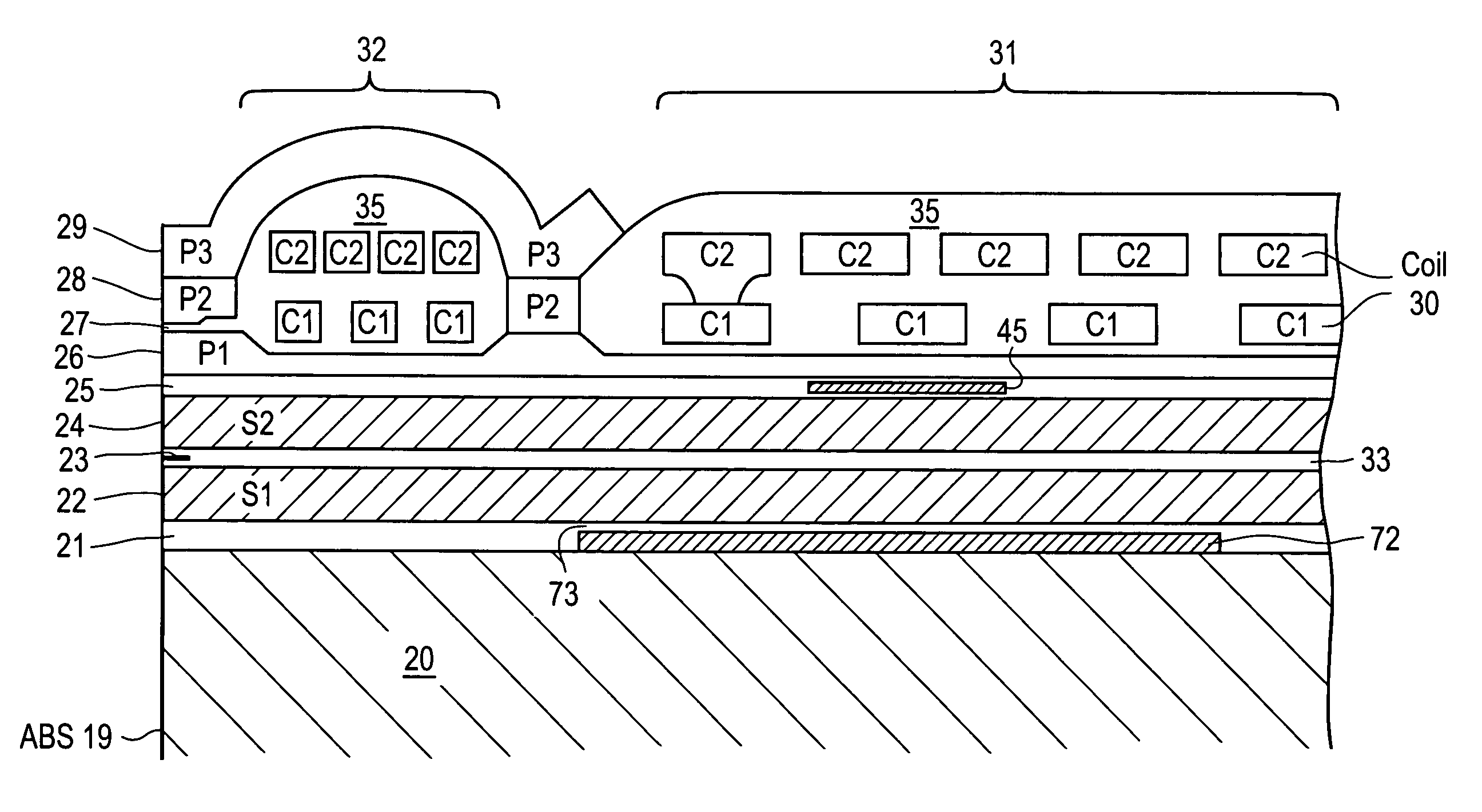
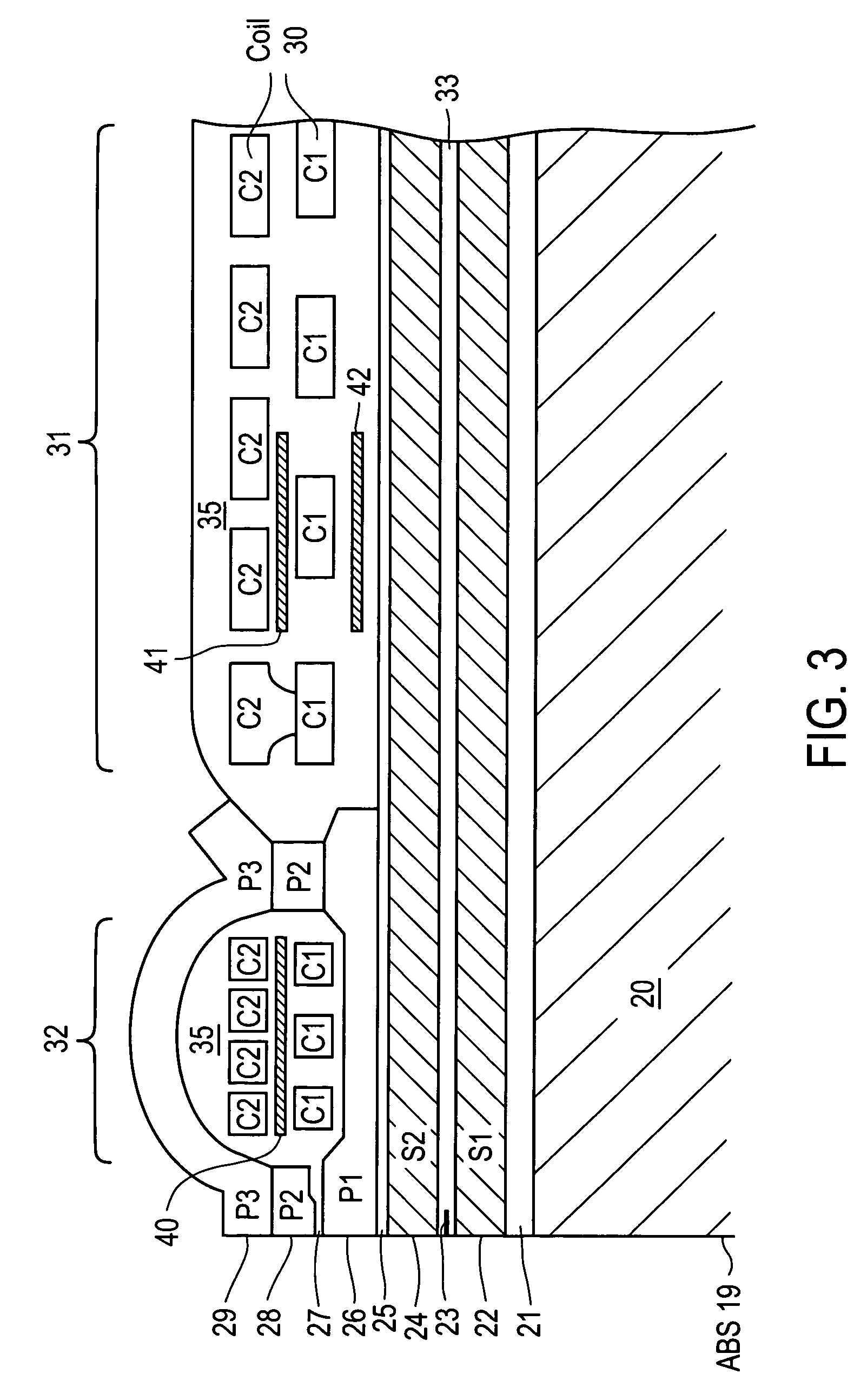
[0042]In accordance with the present invention, at least a portion of a resistive heating element 40 is located between the C1 & C2 coil layers of the first set of turns 32 of coil 30. That is, the C1 & C2 layers of coil 30 are respectively disposed in first and second general planes, and a resistive heating element 40 is disposed in a third general plane between the first and second general planes of coil 30. The first set of turns 32 is disposed nearest to ABS 19, with the second set of turns 31 being disposed farthest from ABS 19. The C1 & C2 layers are embedded within material 35, which material electrically insulates heating element 40 from the turns of coil 30. In the exemplary embodiment of FIG. 4, resistive heating element 40 is shown having a generally annular shape, e.g., like a horseshoe, with the portion illustrated in FIG. 3 being disposed nearest ABS 19, and having first and second arms that extend away from ABS 19.

second embodiment

[0043]In the present invention, a resistive heating element 41 has at least a portion of its constituent material located between the C1 & C2 coil layers of the second set of turns 31 of coil 30. As is shown in the perspective view of FIG. 4, resistive heating element 41 also has the same general annular shape, and is located in the same general plane, as element 40 of the previous embodiment. The primary difference is that element 41 is located farther away from ABS 19. In various implementations, for example, the portion of element 41 shown in FIG. 3 (nearest the air-bearing surface) can be disposed a distance within a range of 20 μm to 60 μm from ABS 19.

third embodiment

[0044]In the present invention, a resistive heating element 42 has the same general shape as heating element 41 and is located within the same distance range from ABS 19 as element 41 of the previous embodiment. The difference between the two embodiments, however, is that resistive heating element 42 is embedded within material 35 between upper shield layer 24 and the C1 layer of the second set of turns 31 of coil 30. Alternatively, heating element 42 may be disposed in nonmagnetic layer 25 below the second set of turns 31 of coil 30. In all other respects, resistive heating element 42 can be the same as element 41 described above.


PUM


Abstract

A thin film magnetic head includes a slider body having a trailing surface meeting an air-bearing surface at a trailing edge. A magnetic read and write elements are disposed along the trailing surface near the trailing edge. The magnetic write element includes write poles and a coil. A portion of a heating element is disposed in a first general plane beneath the coil and above the magnetic read element. At least one thermally-insulating layer of material having a thermal conductivity of less than about 2.0 W/m-K extends in a second general plane substantially beneath the heating element.

Description

RELATED APPLICATIONS[0001]The present application a continuation-in-part (CIP) application of application Ser. No. 11 / 039,635, filed Jan. 18, 2005, entitled “MAGNETIC RECORDING HEAD WITH RESISTIVE HEATING ELEMENT LOCATED NEAR THE WRITE COIL”, which is assigned to the assignee of the present CIP application.FIELD OF THE INVENTION[0002]The present invention relates generally to the field of magnetic recording; more specifically, to methods and apparatus for controlled thermal expansion of thin-film read / write transducers used in magnetic recording heads.BACKGROUND OF THE INVENTION[0003]Electronic data is commonly stored on discs of various types. Disc drives hold and rotate the disc while positioning a read / write head over the disc to read data from it or write data to it. The head typically comprises a read / write transducer formed on the trailing surface of a slider. When the disc media is rotated, a thin film of air forms between the disc and an air bearing surface (ABS) of the slid...

Claims


Application Information

Patent Timeline
IPC IPC(8): G11B5/147
CPCG11B5/3133G11B5/6064G11B5/6005G11B5/607
Inventor SONG, SUPINGJIANG, HAIMILLER, CHARLES W.STOEV, KROUM
Owner WESTERN DIGITAL TECH INC
Why Eureka
Try Eureka