30-pin connector

a technology of connectors and connectors, applied in the direction of coupling bases/cases, coupling device connections, incorrect coupling prevention, etc., can solve the problems of device failure, pin and socket alignment becoming both more difficult and critical, and adding a level of complexity to the manufacture of parts

Inactive Publication Date: 2008-09-30
MONSTER
View PDF5 Cites 40 Cited by
  • Summary
  • Abstract
  • Description
  • Claims
  • Application Information

AI Technical Summary

Benefits of technology

[0006]Accordingly, the preferred embodiment of the present invention is an easily manufactured miniaturized connector having two elements or portions in which the sidewall of a shoulder formed on each side of the plug portion cooperates with a sidewall on each side of the receiver portion so that alignment of the plug with the receiver is automatically achieved as the plug is inserted into the receiver, thereby providing precise alignment of the pins with their respective sockets.
[0008]The receiver is manufactured with a recess sized to closely accept the protrusion of the plug. The recess is of a depth sufficient to guide and protect the plug protrusion as it is fully inserted therein, resulting in physical connection of each pin with its associated socket. In a first embodiment of the connector, the sidewalls of the recess are formed with shoulders which cooperate with the edge shoulders of the plug protrusion, thereby providing for proper alignment of the pins prior to their contact with the receiver terminals or sockets. In a second embodiment of the connector, the sidewalls of the recess are smooth and cooperate with the edges of the wider second surface of the plug protrusion, thereby also providing for proper alignment of the pins prior to their contact with the receiver terminals or sockets.

Problems solved by technology

While the proper alignment of pins with sockets was not a significant problem when connectors and pins were relatively bulky and pins were surrounded by thicker insulation or separated by greater distances, as connectors became smaller and smaller, pin and socket alignment became both more difficult and critical.
Miniaturized connectors are especially vulnerable to misalignment problems which could easily lead to device failures.
These approaches taught by Kuroda et al. and Kuboda et al. to facilitating pin alignment during joining of the connector portions have, however, two deficiencies; they add a level of complexity to the manufacture of the portions (e.g. milling of slits or grooves and the need for precise alignment of projections and slits or grooves) and the ribs or projections are subject to deformation or wear during repetitive matings of the two connector portions, thereby losing the necessary precision.

Method used


Image

  • 30-pin connector
  • 30-pin connector
  • 30-pin connector

Examples


Embodiment Construction

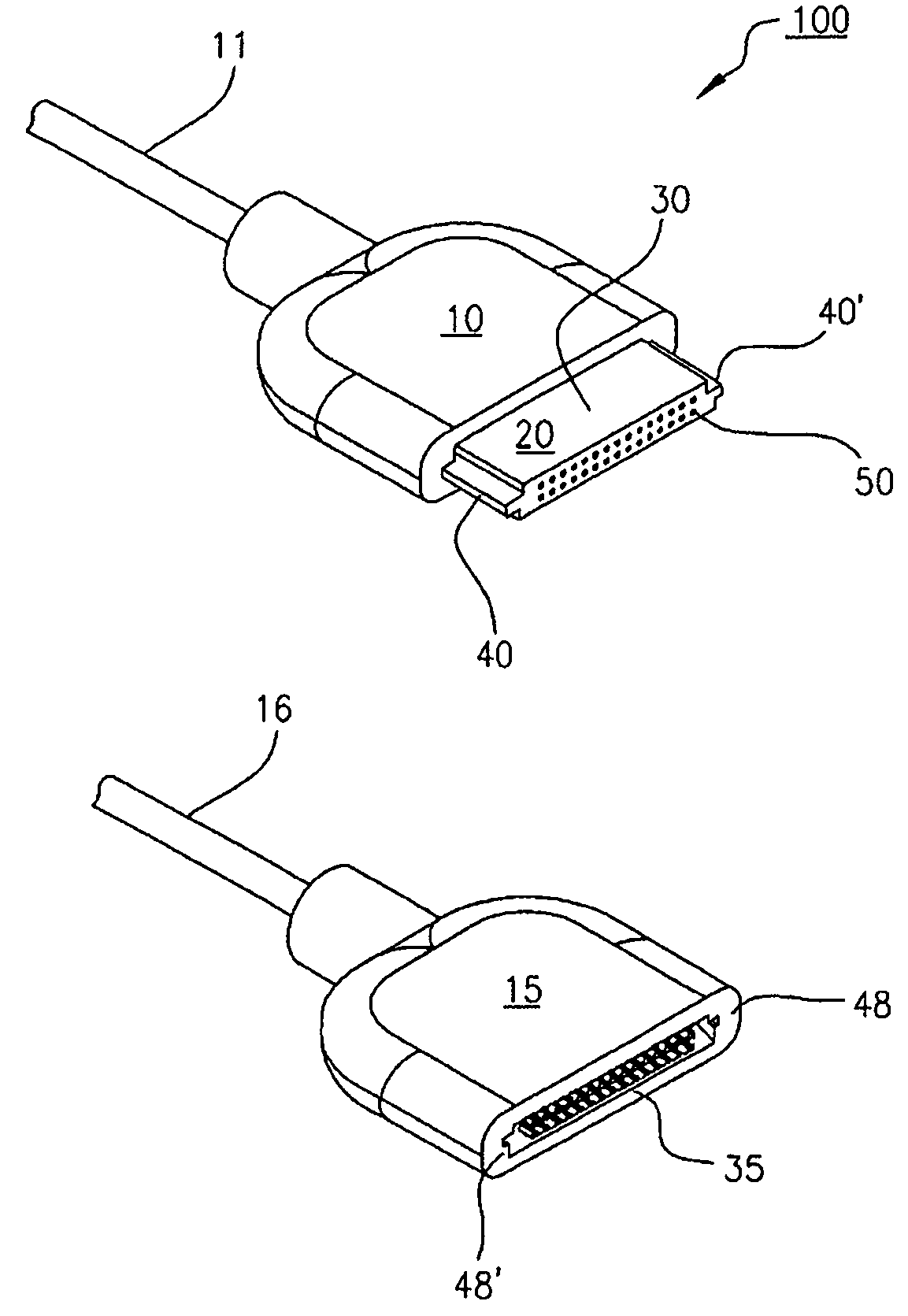
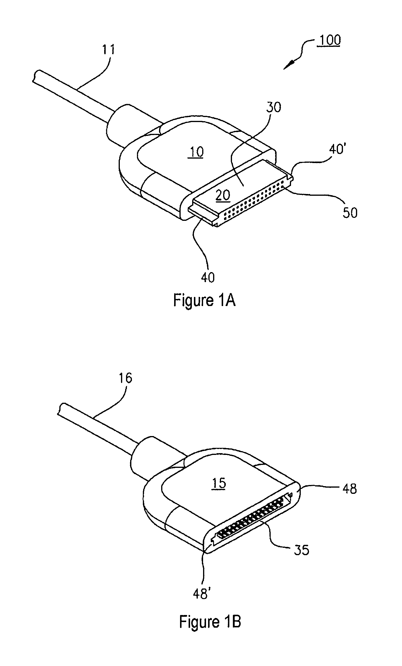
[0019]Referring now to FIGS. 1A, 3, and 4, a first exemplary embodiment of a connector plug 100 according to the present invention is shown. Cable 11 represents cooperation with another device such as a cable to a device or a physical connection to a component for connection with another component. It is to be further understood for the purposes of this application that the plug may be an integral part of a component to be installed on a circuit board which would then contain the receiver element.

[0020]Body 10 may be formed of any suitable material, preferably plastic but metal may also be suitable. Body 10 and tongue or protrusion 20 may be of the same material or of different materials. Plug 100 preferably comprises a relatively flat box shape but other shapes are contemplated by the present invention. The exterior of the plug may take any convenient shape, having, for example, smooth surfaces, stippling, checkering, or recesses in any combination to facilitate grasping the plug o...


PUM


Abstract

An easily manufactured miniaturized connector in which a shoulder formed on each side of the plug portion cooperates with a cooperating sidewall bearing surface on each side of a recess in the receiver portion so that alignment of the plug with the receiver is automatically achieved as the plug is inserted into the receiver, thereby minimizing misalignment of terminals in the plug and receiver.

Description

FIELD OF INVENTION[0001]The present invention relates to connectors used for making a connection between two electronic devices, more particularly to connectors having a plethora of terminals for making multiple simultaneous connections, and even more particularly to miniaturized connectors having multiple terminals for connecting together elements of miniaturized electronic devices.DESCRIPTION OF RELATED ART[0002]It is common in the field of electronic devices to fabricate components that are separable from other components and functionally joined together by connectors having at least two portions, commonly referred to as a plug portion and a receiver portion. The plug, or male, portion is insertable into the receiver, or female, portion in such a way to make contact between terminals, or pins, carried in the plug with terminals or sockets provided in the receiver. Such connections may occur, for example, between circuit boards and components, or between cables and components or o...

Claims


Application Information

Patent Timeline
Patent Type & Authority Patents(United States)
IPC IPC(8): H01R13/648
CPCH01R9/03H01R13/6456H01R13/46
Inventor WEIS, JARRETLARIVIERE, F. DAVID
Owner MONSTER
Why Eureka
Try Eureka