System and method for increasing image quality in a display system

a display system and image quality technology, applied in the field of systems and methods for displaying images, can solve the problems of reducing the contrast ratio of the display system, difficult to achieve pure black, so as to achieve the effect of increasing image quality

Active Publication Date: 2008-09-30
TEXAS INSTR INC
View PDF3 Cites 7 Cited by
  • Summary
  • Abstract
  • Description
  • Claims
  • Application Information

AI Technical Summary

Benefits of technology

[0011]These and other problems are generally solved or circumvented, and technical advantages are generally achieved, by preferred embodiments of the present invention which provides a system and a method for increasing image quality by eliminating vias on a reflective surface.
[0015]An advantage of a preferred embodiment of the present invention is that the vias on the surface of the mirrors are completely filled, which will maximize the brightness of the display system. Additionally, no material from the mirror surface needs to be removed. The removal of material from the mirror can weaken the mirror, making the mirror prone to damage over use. Furthermore, the removal of the material from the mirror can damage the support structure of the mirror.
[0016]Yet another advantage of a preferred embodiment of the present invention is that larger mirror vias can be created. The larger via can improve the step coverage, which can yield more reliable mirrors, without compromising contrast ratio (due to the larger via surface area to mirror surface area ratio).
[0017]A further advantage of a preferred embodiment of the present invention is that the coverage of the vias is consistent across multiple mirrors, multiple dies, and multiple wafers, which will yield a more consistent contrast ratio for arrays of light modulators manufactured in the same fabrication line. This results in a more consistent level of performance for display systems utilizing the arrays of light modulators.

Problems solved by technology

The display of pure black can often be difficult to achieve in many display systems, since it is typically not feasible to simply turn off a light source used to display the images when there is a need to display the pure black.
Since it is not possible to turn off the light, it can be very difficult to achieve pure black.
The scattered light that reaches the display plane can lighten the darkest displayable gray scale and therefore reduce the contrast ratio of the display system.
However, since the micromirror must be able to reflect as much light as possible (to maximize the brightness of the display system), to coat the micromirror with an antireflective coating will only reduce the perceived quality of the images displayed by the display system.
One disadvantage of the prior art is that reducing the surface area of the via 105 can result in making the formation of the physical structure of the micromirror more difficult.
Furthermore, a reduction in the size of the via 105 may reduce the reliability of the attachment of the micromirror 100 to the hinge (reduced step coverage).
Another disadvantage of the prior art is that the placement of an antireflective coating 120 into the via 105 can be hard to control and some of the antireflective coating can end up deposited onto the surface of the micromirror 100 or the via 105 may not be fully coated, resulting in either a loss of brightness or scattered light.
Yet another disadvantage of the prior art is that the polishing of the mirror surface to remove the coating can remove some of the material of the mirror surface, thereby potentially damaging the mirror surface.
Additionally, the removal of the material of the mirror surface can weaken the mirror surface, making the mirror open to damage during use.

Method used


Image

  • System and method for increasing image quality in a display system
  • System and method for increasing image quality in a display system
  • System and method for increasing image quality in a display system

Examples


Embodiment Construction

[0025]The making and using of the presently preferred embodiments are discussed in detail below. It should be appreciated, however, that the present invention provides many applicable inventive concepts that can be embodied in a wide variety of specific contexts. The specific embodiments discussed are merely illustrative of specific ways to make and use the invention, and do not limit the scope of the invention.

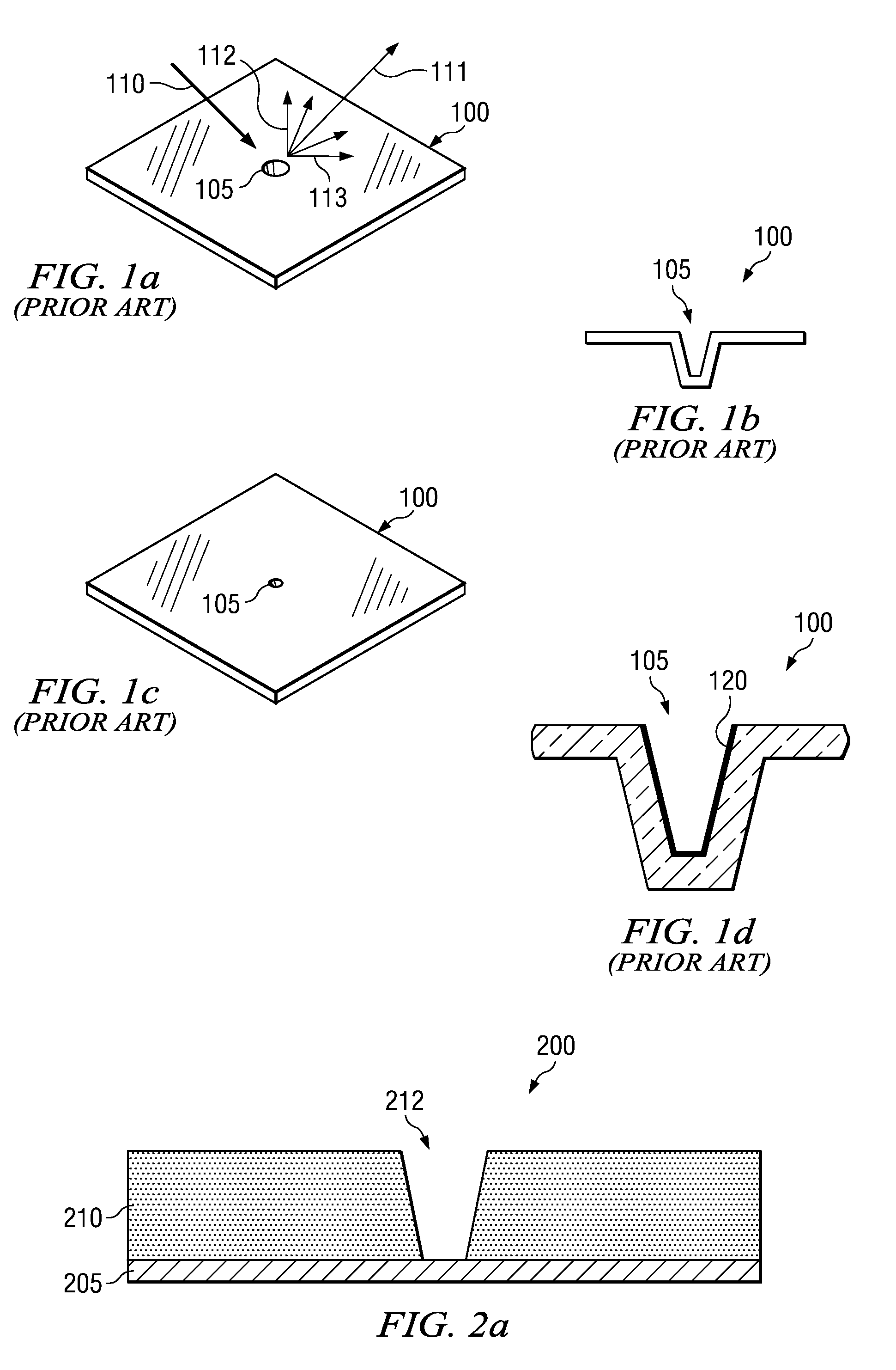
[0026]The present invention will be described with respect to preferred embodiments in a specific context, namely the fabrication of a mirror surface of a micromirror light modulator for use in display systems. The invention may also be applied, however, to other surfaces wherein there is a desire to fill in vias and holes present on the surface.

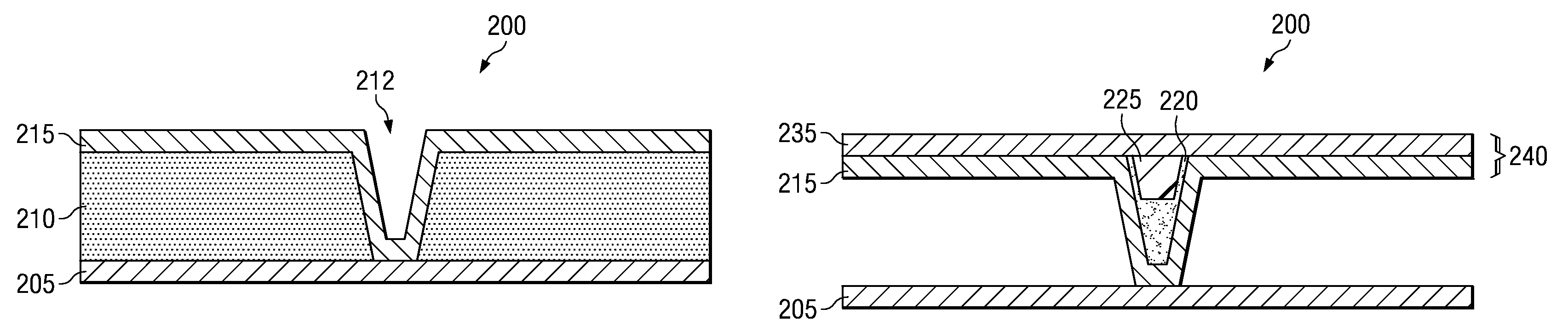
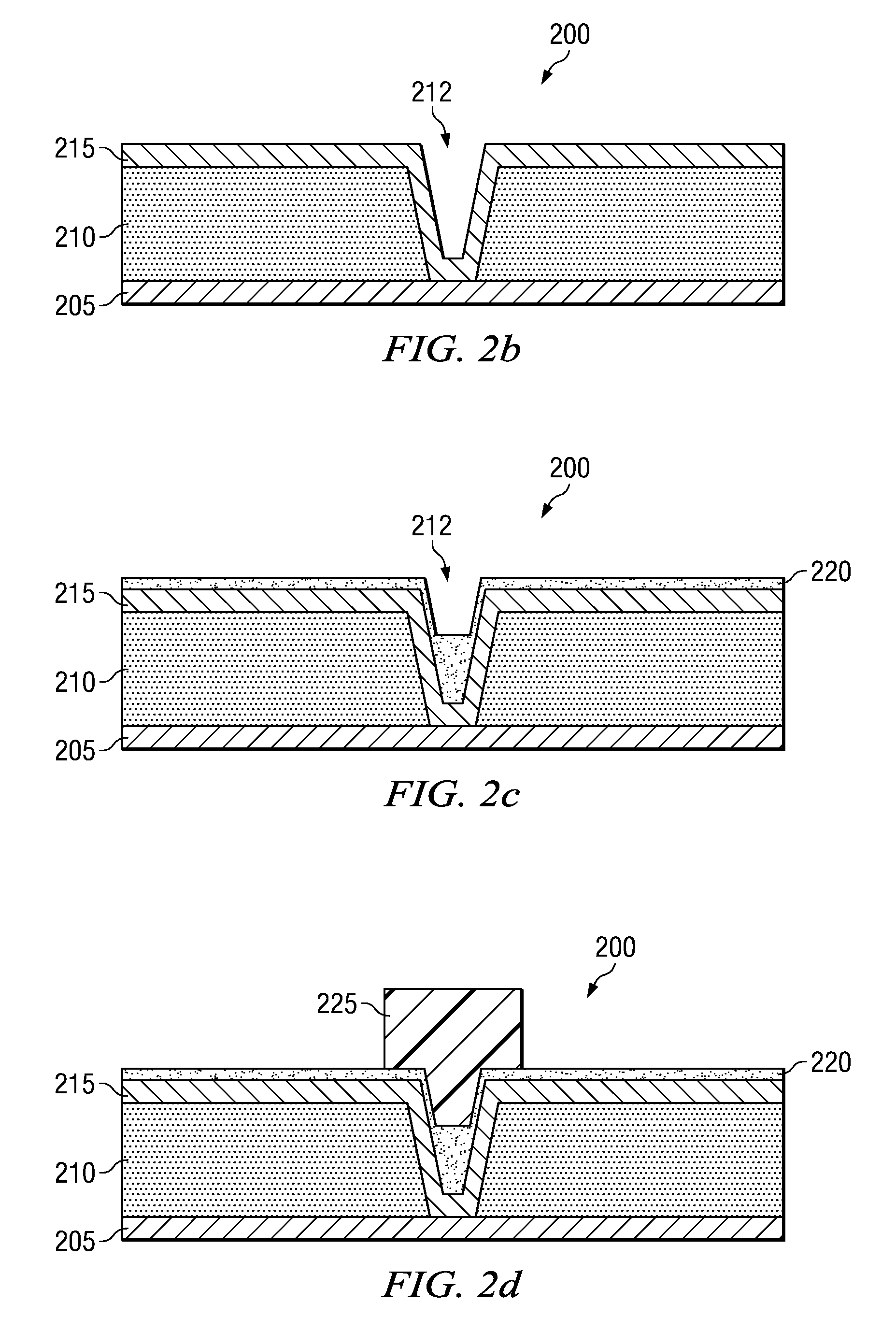
[0027]With reference now to FIGS. 2a through 2j, there are shown diagrams illustrating exemplary cross-sectional views of a micromirror light modulator 200 during the fabrication of the micromirror light modulator 200, wherein a via o...


PUM

PropertyMeasurementUnit
diameteraaaaaaaaaa
thicknessaaaaaaaaaa
brightnessaaaaaaaaaa

Abstract

System and method for maximizing image quality by eliminating vias on a reflective surface. A preferred embodiment comprises depositing a first portion of a mirror surface over a support surface, applying a protective coating on the mirror surface, and then inverting the via. The preferred embodiment also comprises removing a portion of the inverted via and then depositing a second portion of the mirror surface. The remaining portion of the inverted via fills the via and provides a level surface for the depositing of the second portion of the mirror surface, reducing the amount of light scattered by the via.

Description

TECHNICAL FIELD[0001]The present invention relates generally to a system and a method for displaying images, and more particularly to a system and a method for increasing image quality by eliminating vias on a reflective surface.BACKGROUND[0002]In microdisplay-based display systems used to display images by projecting the images onto a display plane, the contrast ratio of the display system has a significant impact on the perceived quality of the system. A display system's contrast ratio can be defined as a ratio of the brightest displayable gray scale (typically, pure white) to the darkest displayable gray scale (usually, pure black). The display of pure black can often be difficult to achieve in many display systems, since it is typically not feasible to simply turn off a light source used to display the images when there is a need to display the pure black. Rather, light from the light source is normally redirected so that the amount of light projected onto the display plane is m...

Claims


Application Information

Patent Timeline
Patent Type & Authority Patents(United States)
IPC IPC(8): G02B26/00B29D11/00G03C5/00
CPCG02B26/0833G02B5/0858
Inventor ROTH, RONALD CHARLESHOGAN, TIMOTHY JOSEPHSHERWIN, LUCIUS
Owner TEXAS INSTR INC
Why Eureka
Try Eureka