Dispensing machine to store and dispense elongated containers vertically

a technology of elongated containers and dispensers, which is applied in the direction of coin-freed apparatus, pile separation, application, etc., can solve the problems of difficult removal of clusters described in the previous application from the remaining clusters achieves the effects of easy removal and replacement without tools, lightweight, inexpensive and durabl

Inactive Publication Date: 2008-10-07
BARRYCO TECH
View PDF7 Cites 12 Cited by
  • Summary
  • Abstract
  • Description
  • Claims
  • Application Information

AI Technical Summary

Benefits of technology

[0006]It is an object of the present invention to provide a dispensing machine whereby any number of clusters can be easily removed from the machine and replaced without tools. It is a further object of the present invention to provide an improved dispensing machine that is lightweight, inexpensive and durable and a machine in which the columns will not twist as the actuator rotates.
[0007]A dispensing machine for elongated containers having a neck at a top thereof comprises at least three vertical columns arranged adjacent to one another to form a cluster. The cluster has an interstice between the columns with an actuator mounted therein. The columns of each cluster are affixed to one another and the actuator has a lower platform and an upper platform. The columns have openings therein to receive the upper platform. Each platform is substantially perpendicular to the longitudinal axis of each column of the cluster. The platforms are mounted on a shaft with means to rotate said shaft by successive steps to eject one container from each machine for each step. The lower platform is located at a base of the cluster, the upper platform being located above the lower platform by a distance that is less than a height of one of the containers. The lower platform is larger than the upper platform, the containers being stored on top of one another in the columns in an upright position. The lower platform has a cutaway portion and is sized to block all of the columns except one in each position of the shaft. The upper platform is located at a level of the neck and is oriented to block one column that is not blocked by the lower platform in each position of the shaft. A first bracket extends between the columns near the base. The first bracket has an enlarged central portion that substantially fills the interstice. The shaft extends through the center portion, the first bracket having two ends extending outward from the center portion between the columns. The ends are removably affixed to a retainer, the retainer supporting the cluster including the actuator, and the retainer and first bracket preventing the columns from twisting as the actuator rotates.

Problems solved by technology

The clusters described in the previous application cannot be easily separated from the remaining clusters and replaced without tools.

Method used


Image

  • Dispensing machine to store and dispense elongated containers vertically
  • Dispensing machine to store and dispense elongated containers vertically
  • Dispensing machine to store and dispense elongated containers vertically

Examples


Embodiment Construction

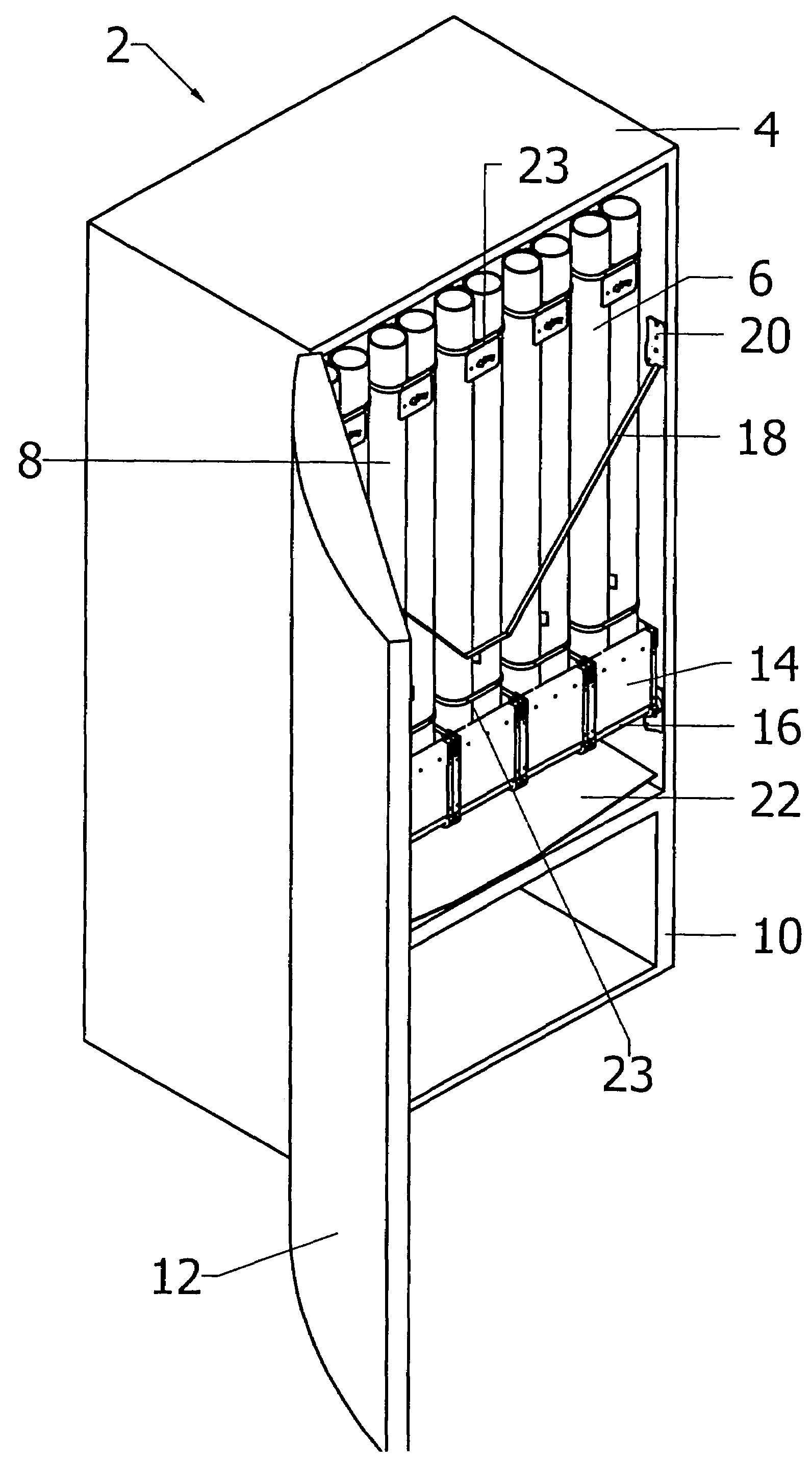
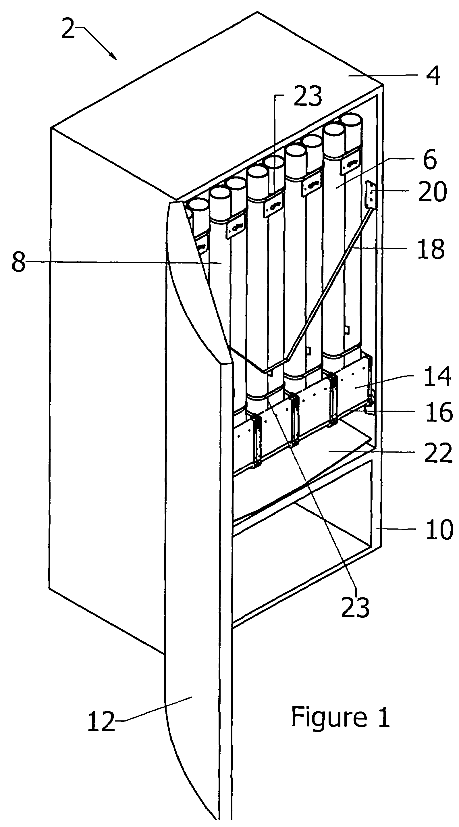
[0047]In FIG. 1, there is shown a dispensing machine 2 having a housing 4 containing fifteen clusters 6 of tubes 8 only five of the clusters 6 being partially shown. The housing 4 has a front 10 and a door 12 that is in an open position. The refrigeration equipment, or temperature control equipment and the wiring of the dispensing machine are considered to be conventional and are not described unless expressly stated. Each set of three clusters has a front plate 14 with a pivot bar 16 extending across the front 10 of the housing 4. A strap 18 is releasably attached to an inside wall mount 20. The strap 18 holds the clusters in position so that they will not tilt forward. A chute 22 provides an exit through an outlet in the door (not shown) for any containers that exit from the clusters 6. The clusters 6 are bound together at top and bottom by bindings 23.

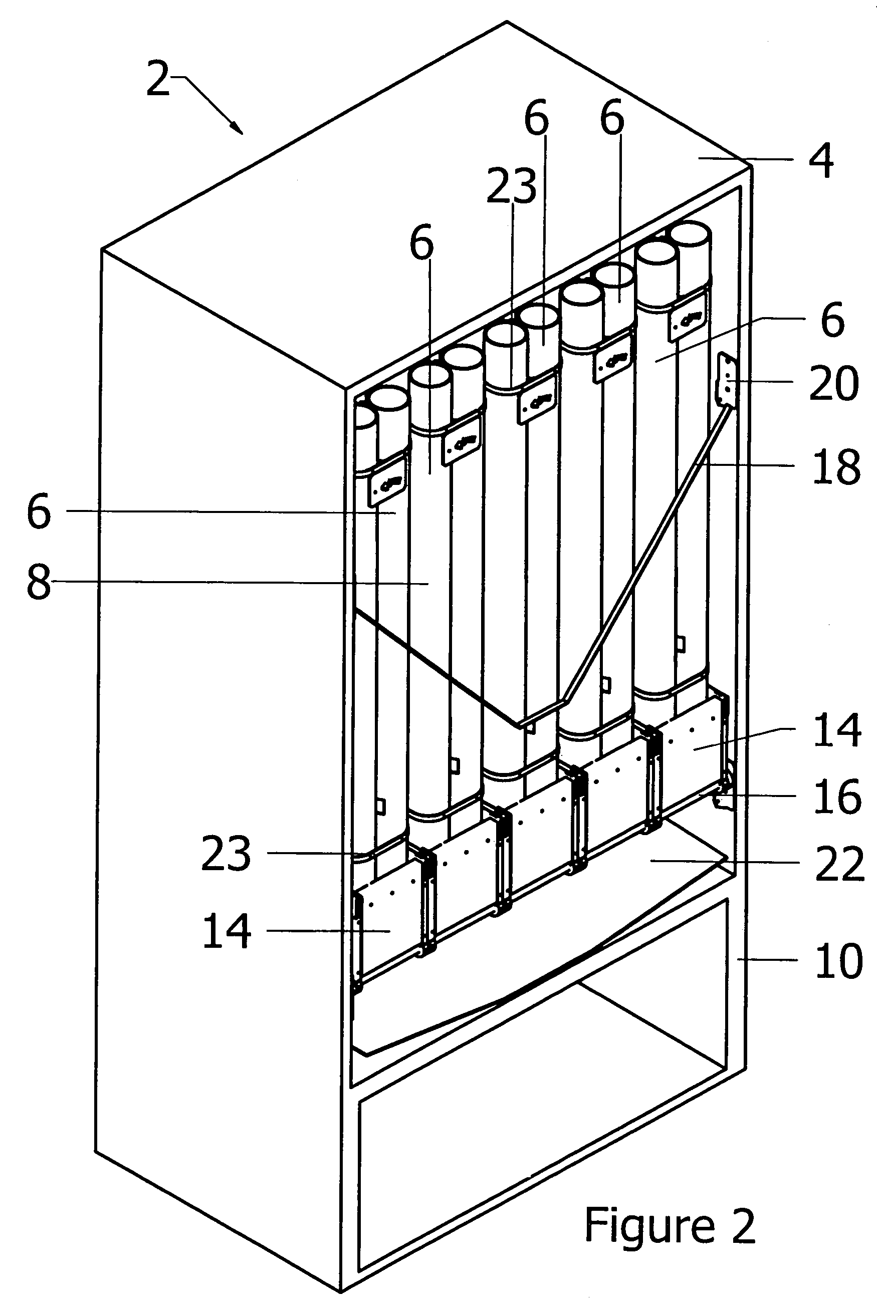
[0048]In FIGS. 2, 3 and 4, the same reference numerals are used to describe those components that are identical to the components ...


PUM


Abstract

A dispensing machine for elongated containers has a plurality of clusters arranged within a housing. The clusters each have an actuator and comprise four tubes that are bound together with an interstice along a central axis of the cluster. The actuator is mounted in the interstice and each cluster is supported by a first bracket. A plurality of clusters are mounted from front to rear in the housing with the first brackets being removably mounted in a retainer. The clusters in the retainer form a set and can be tilted forward to replenish the tubes with containers. There are several sets side by side within the housing. The clusters of each set are held in place by one attachment that can be opened without tools to remove the clusters of that set.

Description

BACKGROUND OF THE INVENTION[0001]1. Field of the Invention[0002]This invention relates to a dispensing machine for elongated containers of beverages and the like whereby said containers are stored vertically and automatically dispensed from said machine. More particularly, this invention relates to a dispensing machine having a plurality of vertical columns formed into clusters with one actuator for each cluster in which the clusters can be easily removed and replaced in the machine. The invention further relates to a method of constructing such a machine.[0003]2. Description of the Prior Art[0004]Applicant is the inventor named in U.S. Pat. No. 6,902,084 for a Container Dispenser. Usually, the containers contain beverages and the beverages are often what is commonly referred to as water, flavoured water, sports drinks or pure juices. The containers are often made from plastic and are weak laterally, but strong longitudinally. The beverages can be carbonated or non-carbonated. When ...

Claims


Application Information

Patent Timeline
Patent Type & Authority Patents(United States)
IPC IPC(8): B65G59/00
CPCA47F1/10G07F11/24G07F11/10A47F7/28
Inventor BAUMAN, BARRY B.
Owner BARRYCO TECH
Why Eureka
Try Eureka