
Photoreceptors, developing cartridge using the same, and image forming apparatus using the same

a technology of developing cartridges and photoreceptors, which is applied in the direction of electrographic process apparatus, instruments, corona discharge, etc., can solve the problems of difficult fine control of the developing nip and the developing gap, image may be uneven or contain unprinted voids, and the tone image failure may occur on the photoreceptor drum, so as to improve the location tolerance and the assembly tolerance

Active Publication Date: 2008-10-07
HEWLETT PACKARD DEV CO LP
View PDF7 Cites 60 Cited by
  • Summary
  • Abstract
  • Description
  • Claims
  • Application Information

AI Technical Summary

Benefits of technology

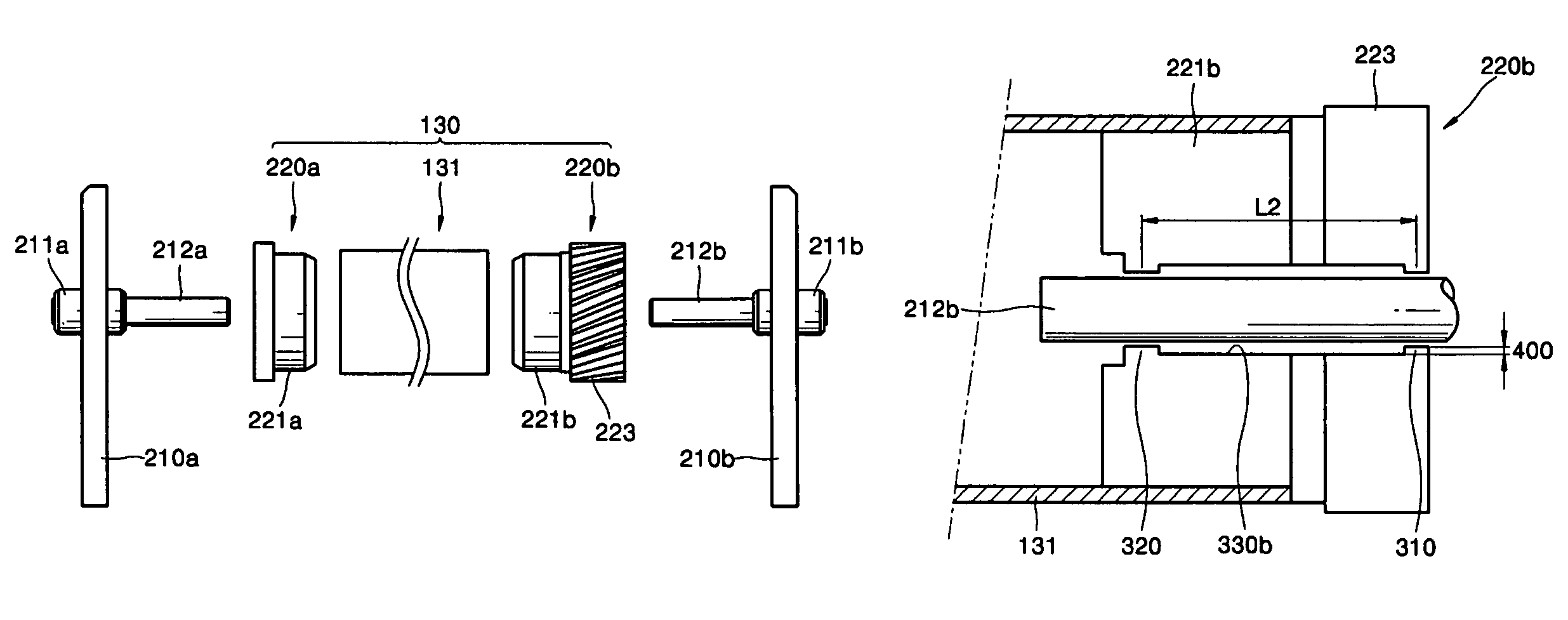
[0010]Various aspects and example embodiments of the present invention provide a photoreceptor drum that can improve a location tolerance and an assembly tolerance without adding additional parts, while ensuring the uniformity of a developing nip and a development gap, and a developing cartridge and an image forming apparatus having the photoreceptor drum.

Problems solved by technology

If the developing roller and the photoreceptor drum are not correctly aligned, tone image failure may occur on the photoreceptor drum.
That is, an image may be uneven or contain unprinted voids.
However, fine control of the developing nip and the developing gap is very difficult.
As the contact area between the shaft and the photoreceptor drum increases, the management of the manufacture and assembly tolerances becomes increasingly difficult.
However, if the contact area is too small, the shaking of the shaft with respect to the sleeves of the photoreceptor drum may occur, and the photoreceptor drum may not stay in parallel to the developing roller.
In an image forming apparatus that prints a color image, the number of developing rollers and photoreceptor drums increases, thereby increasing the difficulty of maintaining a uniform developing nip and developing gap.

Method used


Image

  • Photoreceptors, developing cartridge using the same, and image forming apparatus using the same
  • Photoreceptors, developing cartridge using the same, and image forming apparatus using the same
  • Photoreceptors, developing cartridge using the same, and image forming apparatus using the same

Examples


Embodiment Construction

[0025]Reference will now be made in detail to the present embodiments of the present invention, examples of which are illustrated in the accompanying drawings, wherein like reference numerals refer to the like elements throughout. The embodiments are described below in order to explain the present invention by referring to the figures.

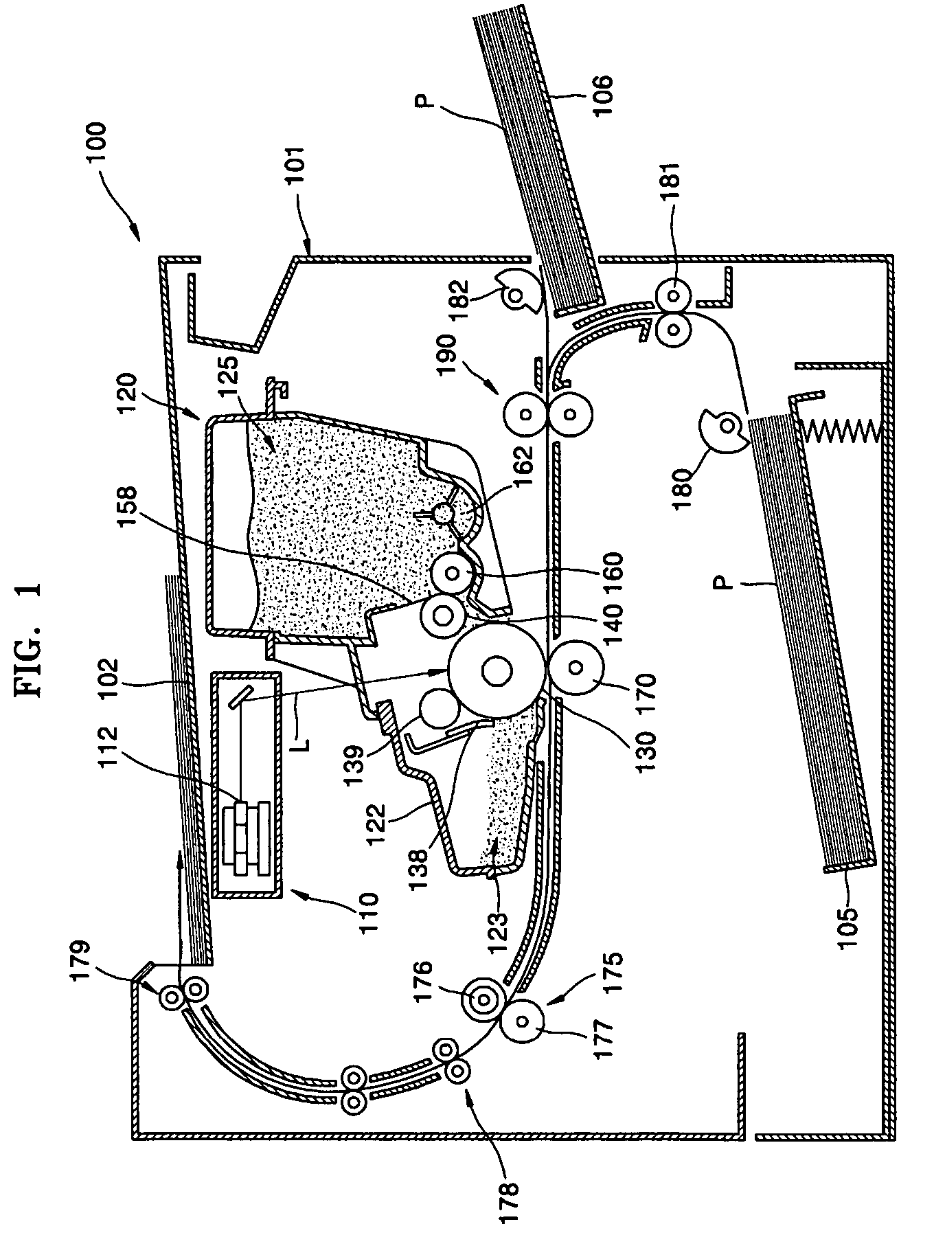
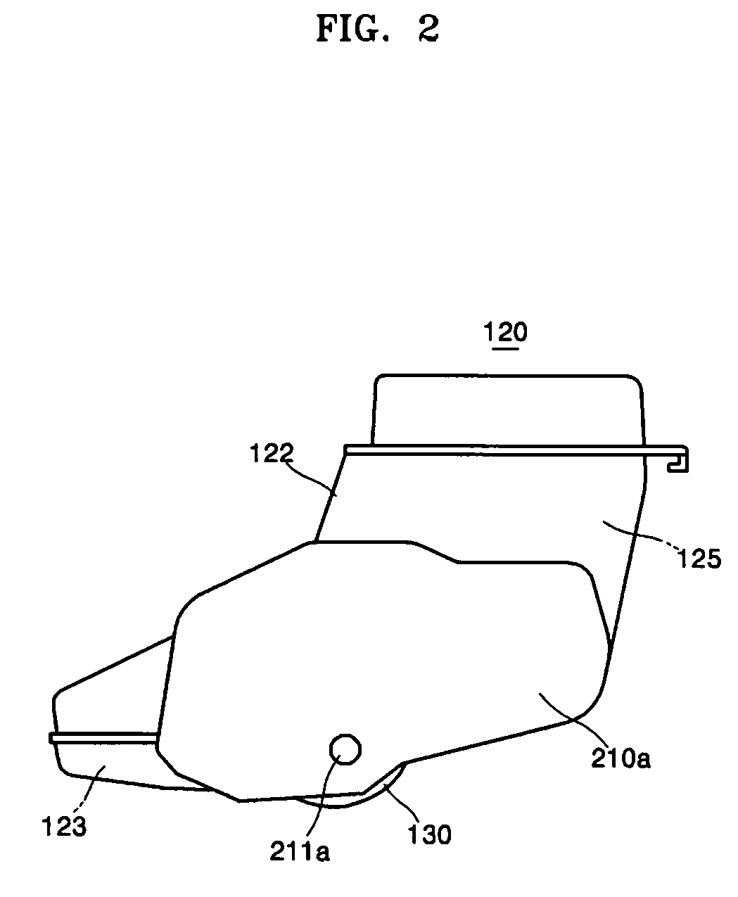
[0026]FIG. 1 is a lateral cross-sectional view of an image forming apparatus according to an embodiment of the present invention. As shown in FIG. 1, the image forming apparatus 100 comprises a main body 101 that forms an image on a recording medium, such as paper, using an electrophotographic method, a photoreceptor drum 130 located in the main body 101, and a pair of shafts 212a and 212b (as shown in FIG. 4) that support the ends of the photoreceptor drum 130. The image forming apparatus main body 101 includes a laser scanning unit 110; a developing cartridge 120; a fixing unit 175; a de-curl unit 178; a pickup assembly including a first pickup rolle...


PUM


Abstract

A developing cartridge and an image forming apparatus having a photoreceptor drum are provided. The photoreceptor drum includes a pair of sleeves having outer diameter units inserted into the ends of a cylindrical drum on which a photoconductive material layer is formed, inner diameter units to which shafts are rotatably coupled, and at least two protrusion units separated from each other in a length direction of the shafts and contacting the shafts by protruding from the inner diameter units. Accordingly, the location tolerance and the assembly tolerance of the photoreceptor drum can be reduced by only modifying the shape of the sleeves, without adding additional parts. As a result, printing defects such as voids and unevenness can be advantageously prevented, since the developing nip and developing gap are formed very uniformly.

Description

CROSS-REFERENCE TO RELATED PATENT APPLICATION[0001]This application claims all benefits accruing under 35 U.S.C §119 from Korean Patent Application No. 10-2005-0033547, filed on Apr. 22, 2005, in the Korean Intellectual Property Office, the disclosure of which is incorporated by reference herein.BACKGROUND OF THE INVENTION[0002]1. Field of the Invention[0003]The present invention relates to photoreceptor drums, and a developing cartridge and an image forming apparatus having the photoreceptor drums, and more particularly, to photoreceptor drums in which assembling tolerances are improved to maintain a uniform developing gap or a uniform developing nip, and a developing cartridge and an image forming apparatus having the photoreceptor drums.[0004]2. Related Art[0005]Electrophotographic image forming apparatuses, such as printers, photocopiers, facsimile machines and multi-functional products, are devices for printing an image on a recording medium, such as a paper, by an electrophoto...

Claims


Application Information

Patent Timeline
Patent Type & Authority Patents(United States)
IPC IPC(8): G03G15/00
CPCG03G15/751G03G15/06G03G15/0822G03G15/348G03G21/181G03G2215/0634G03G2217/0075
Inventor KWEON, DAE-SEOBKIM, YOUNG-MIN
Owner HEWLETT PACKARD DEV CO LP
Learn More