Angular ejector mechanism and injection mold with the same

a technology of which is applied in the field of angular ejector mechanism and injection mold with the same, can solve the problems of easy damage of plastic articles, increased manufacturing costs, and difficulty in ejecting plastic articles with a big dimension in the inner sides

Inactive Publication Date: 2008-10-14
CHENG UEI PRECISION IND CO LTD
View PDF12 Cites 26 Cited by
  • Summary
  • Abstract
  • Description
  • Claims
  • Application Information

AI Technical Summary

Benefits of technology

[0007]It is another object of the present invention to provide an injection mold with the above angular ejector mechanism adapted to mold a plastic article with a big dimension recess and being capable of separating the plastic article conveniently from the injection mold.
[0010]As described above, while the angular ejector pin ejecting the plastic article, the sliding pin slides in the vertical channel to force the angular ejector pin separate from the plastic article, then the sliding pin slides in the inclined channel, the angular ejector pin is completely separated from the plastic article and the elastic element exerts elastic force on the sliding pin to force the moving portion of the sliding pin exit the recess of the plastic article, thus the plastic article is not interfered by the angular ejector pin and sliding pin so as to be conveniently and smoothly ejected from the injection mold. Therefore, the plastic article does not damaged by the angular ejector pin and further to simplify the manufacturing procedure and reduce the manufacturing cost.

Problems solved by technology

However, it is convenient for the angular ejector pin to eject a plastic article having a small dimension recess in inner sides, but it is difficult to eject the plastic article having a recess with a big dimension in inner sides.
If the ejector pin directly ejects the plastic article 200, the plastic article 200 is so tightly matched with the angular ejector pin that the plastic article is easily damaged while the ejector pin ejects the plastic article, and it is time consuming to take the plastic article 200 off the angular ejector pin by hand, thus to increase the manufacture cost.

Method used


Image

  • Angular ejector mechanism and injection mold with the same
  • Angular ejector mechanism and injection mold with the same
  • Angular ejector mechanism and injection mold with the same

Examples


Embodiment Construction

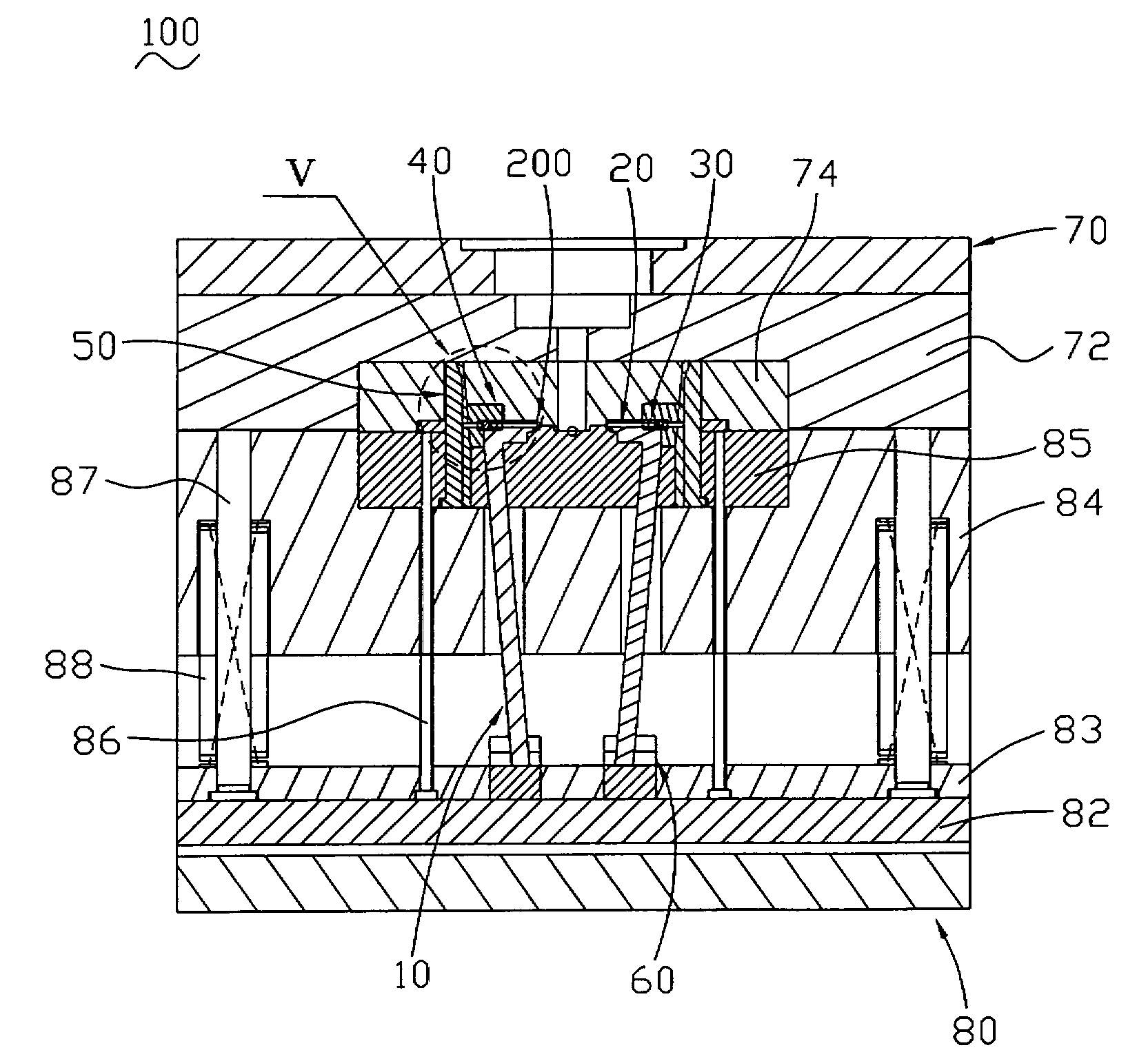
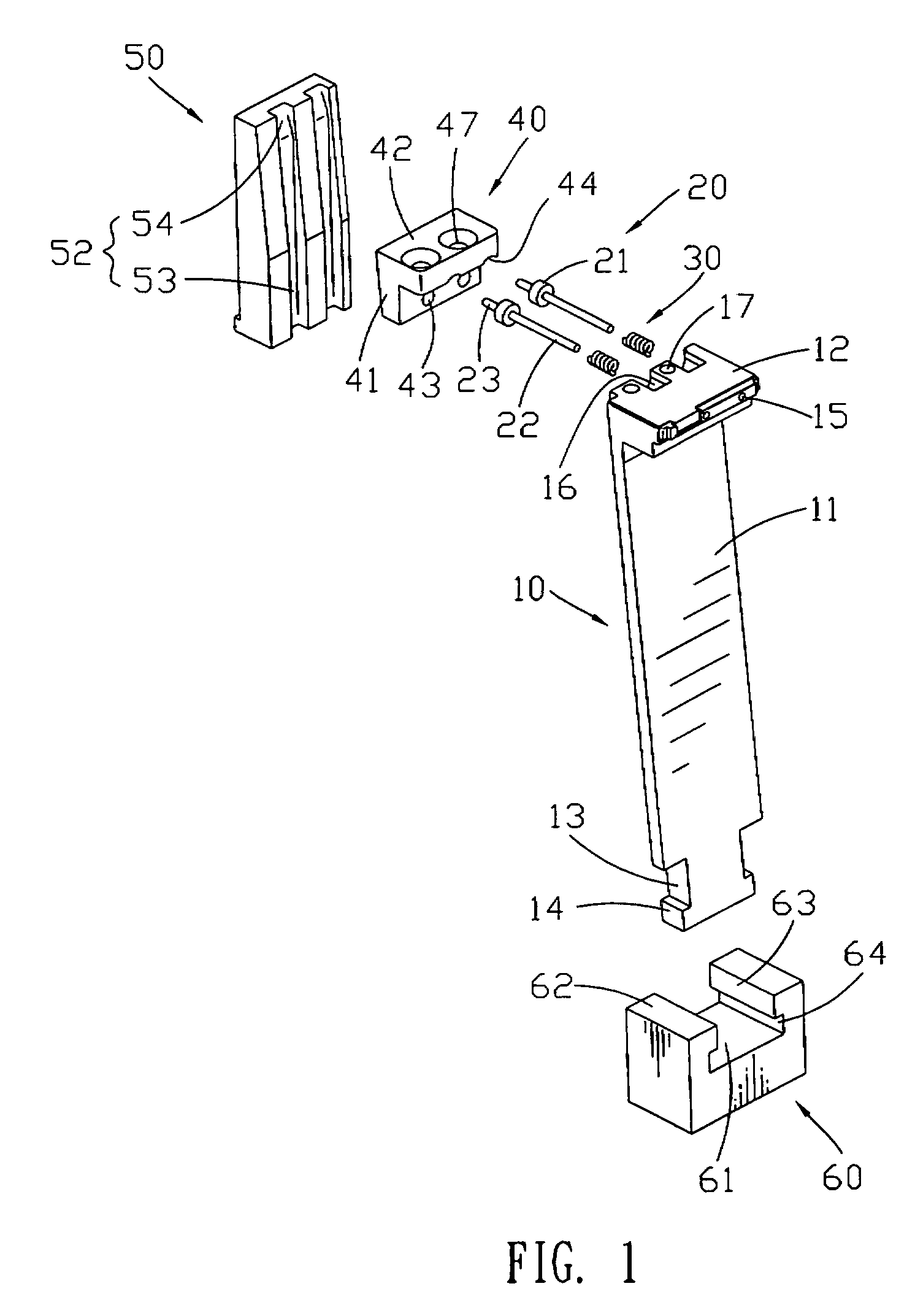
[0025]Referring to FIG. 1, FIG. 2 and FIG. 4, an angular ejector mechanism is mounted in an injection mold 100 for molding a plastic article having a big dimension recess in a inner side and conveniently ejecting the plastic article 200 from the injection mold 100. The angular ejector mechanism comprises an angular ejector pin 10, a sliding pin 20, a pair of elastic element 30, a hell block 40 and a stopping block 50.

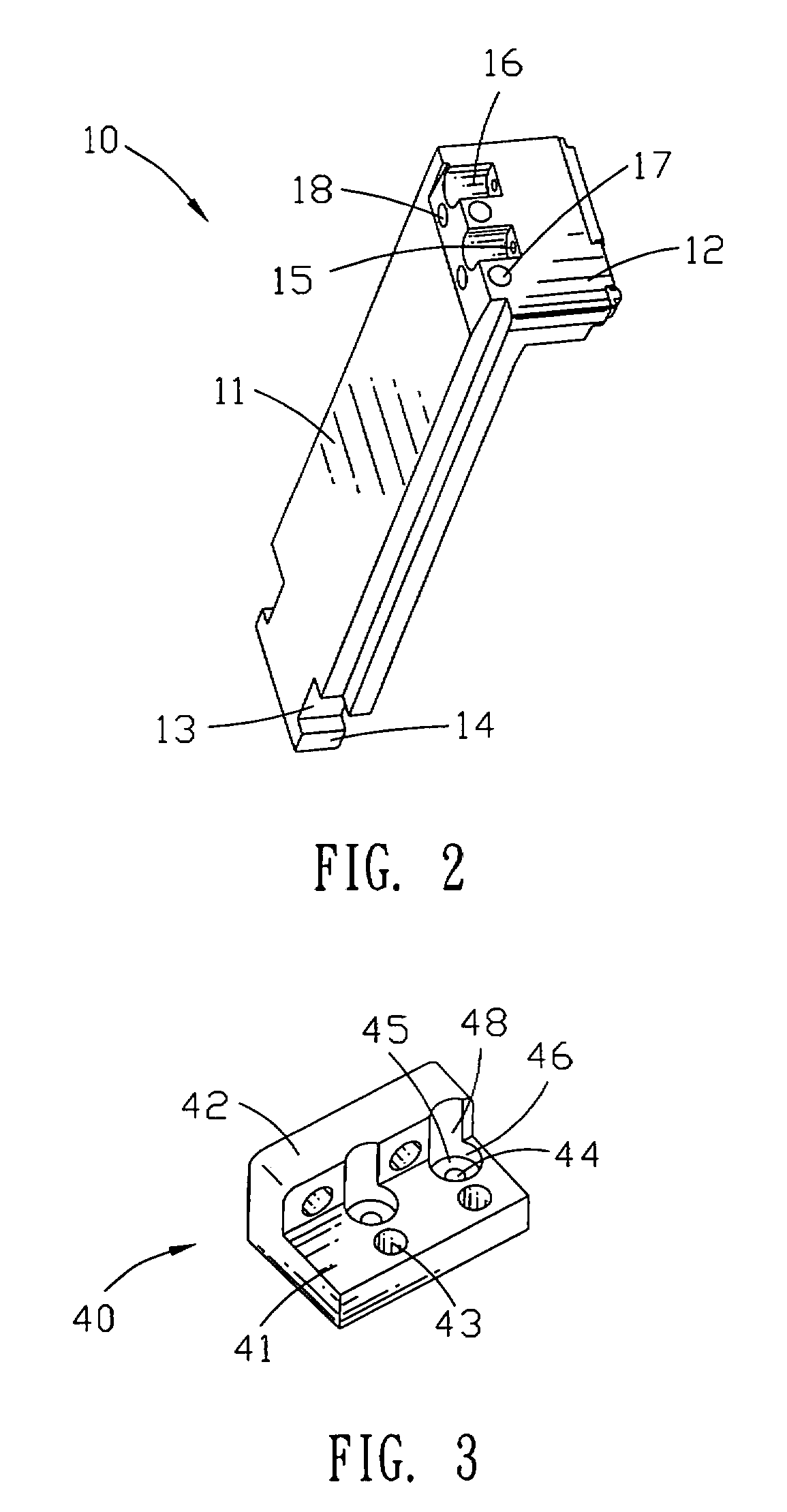
[0026]Referring to FIG. 2, the angular ejector pin 10 includes a horizontal molding plate 12 and an inclined supporting plate 11 extending downward from a portion of the molding plate 12 at a predetermined angle. Two sliding gaps 13 are defined at a lower portion of lateral sides of the supporting plate 11 and two latching protrusions 14 are shaped below the two sliding gaps 13. The molding plate 12 extends forward from an upper portion of the supporting plate 11. The shape and dimension of a front portion of the molding plate 12 is adapted to the shape and dimension of...


PUM

PropertyMeasurementUnit
diametersaaaaaaaaaa
diameteraaaaaaaaaa
elasticaaaaaaaaaa

Abstract

An angular ejector mechanism for ejecting a plastic article with a recess in an inner side includes an angular ejector pin, a sliding pin, an elastic elements and a stopping block. The angular ejector pin includes a molding plate and a supporting plate. A moving hole and a sliding groove are respectively defined in a front face and an opposite rear face of the molding plate to communicate with each other. The sliding pin has a stopping protrusion dividing the sliding pin into a moving portion and a sliding portion. A sliding channel is defined on a front face of the stopping block. The sliding includes a vertical channel and a inclined channel. The moving portion is received in the moving hole of the molding plate, and the sliding portion slides from the sliding channel into the inclined channel until the angular ejector pin separates from the plastic article.

Description

BACKGROUND OF THE INVENTION[0001]1. Field of the Invention[0002]The present invention relates to an angular ejector mechanism for ejecting plastic articles having a recess in inner sides, and also relates to an injection mold with the angular ejector mechanism capable of separating the plastic articles from the injection mold during mold opening cycle.[0003]2. The Related Art[0004]A conventional angular ejector pin in an injection mold is convenient for ejecting a plastic article molded in the injection mold. While mold opening, the angular ejector pin ejects the plastic article out from mold cavities of the injection mold. Then an ejector pin ejects the plastic article out from the injection mold, and meanwhile the plastic article is separated from the angular ejector pin. However, it is convenient for the angular ejector pin to eject a plastic article having a small dimension recess in inner sides, but it is difficult to eject the plastic article having a recess with a big dimensi...

Claims


Application Information

Patent Timeline
Patent Type & Authority Patents(United States)
IPC IPC(8): B29C45/44
CPCB29C45/4005B29C45/44Y10S425/058
Inventor WANG, CHING-CHANGCHEN, CHIH-YUHUANG, JIAN-GUANGHE, YUN-CHUN
Owner CHENG UEI PRECISION IND CO LTD
Why Eureka
Try Eureka