Image forming apparatus with printing medium guide

a technology of image forming apparatus and guide unit, which is applied in the direction of electrographic process apparatus, instruments, optics, etc., can solve the problems of improper registration, difficult manufacture, complicated structure, etc., and achieve the effect of increasing consumption

Inactive Publication Date: 2008-10-14
HEWLETT PACKARD DEV CO LP
View PDF6 Cites 3 Cited by
  • Summary
  • Abstract
  • Description
  • Claims
  • Application Information

AI Technical Summary

Benefits of technology

[0018]An aspect of the present invention is to address at least the above problems and / or disadvantages and to provide at least the advantages described below. Accordingly, an aspect of the present invention is to provide an image forming apparatus which guides a printing medium just before the printing medium moves into a transfer unit to improve transfer efficiency and has a simple guide structure to reduce manufacturing costs.
[0019]Another aspect of the present invention is to provide an image forming apparatus in which photosensitive bodies (photosensitive drums) and waste developer receptacles associated with the photosensitive bodies are integrally formed on a frame. With this construction, the distance between each photosensitive body can be precisely adjusted and the structure for handling waste developer can be simplified.
[0020]Yet another aspect of the present invention is to provide an image forming apparatus in which the waste developer receptacle associated with the photosensitive body with a larger developer consumption rate has a larger volume to minimize the frequency of replacement of the waste developer receptacle.

Problems solved by technology

Conventional guide structures, however, have a complicated structure and are difficult to manufacture.
With existing systems, maintaining appropriate spacing can be difficult, resulting in improper registration and poor image quality.

Method used


Image

  • Image forming apparatus with printing medium guide
  • Image forming apparatus with printing medium guide
  • Image forming apparatus with printing medium guide

Examples


Embodiment Construction

[0045]The matters defined in the description such as a detailed construction and elements are provided to assist in a comprehensive understanding of the exemplary embodiments of the invention. Accordingly, those of ordinary skill in the art will recognize that various changes and modifications of the exemplary embodiments described herein can be made without departing from the scope and spirit of the invention. Also, descriptions of well-known functions and constructions are omitted for clarity and conciseness.

[0046]In the following description, the terms “upstream” and “downstream” will be used with reference to the transfer direction of a printing medium.

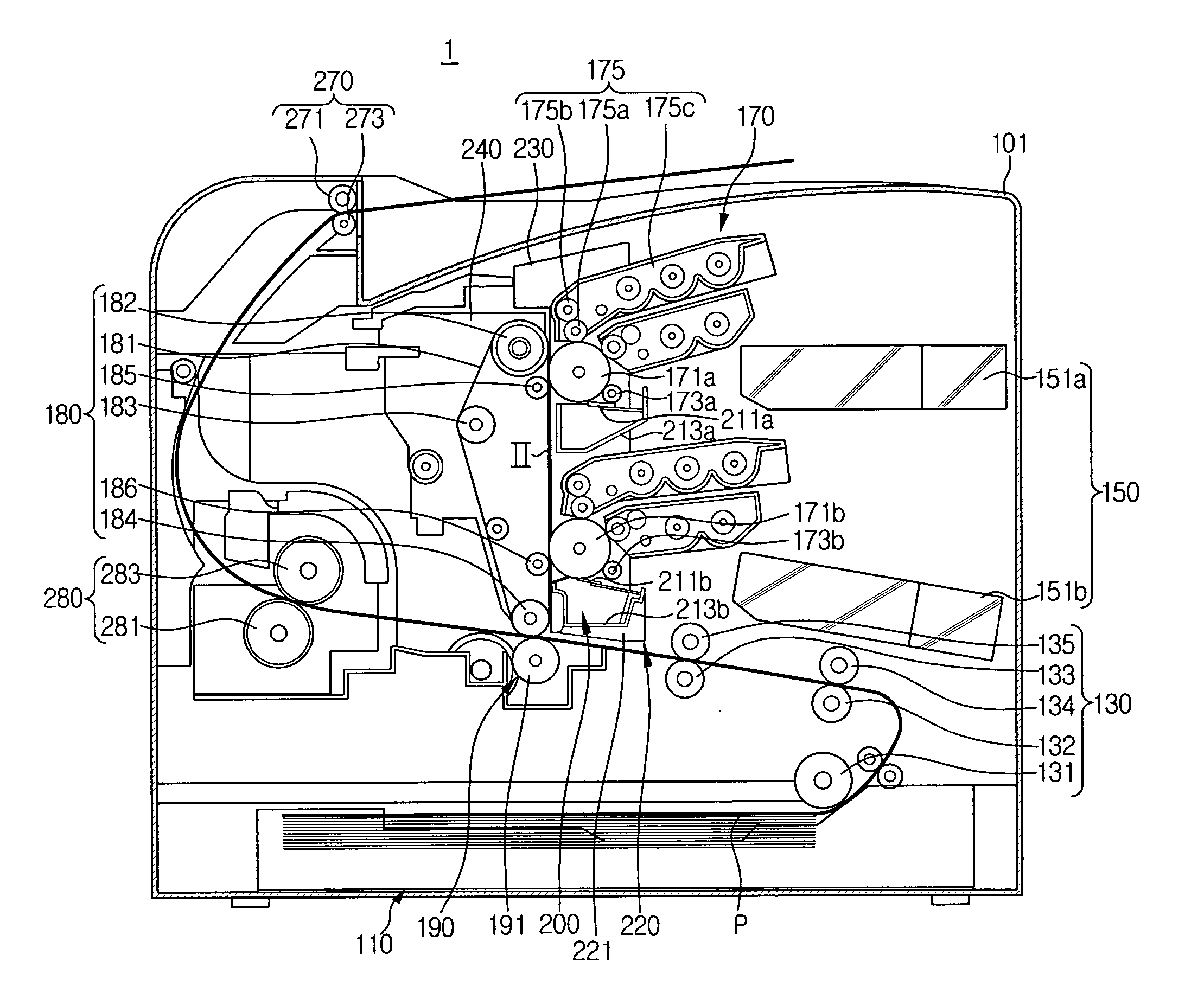
[0047]FIG. 1 is a vertical sectional view of a schematic construction of an image forming apparatus according to an exemplary embodiment of the present invention.

[0048]Referring to FIG. 1, an image forming apparatus 1 comprises a main body 101, a printing medium supply unit 110, a printing medium conveying unit 130, an optical sca...


PUM


Abstract

An image forming apparatus has a photosensitive body on which an electrostatic latent image is formed. A developing unit develops the electrostatic latent image on the photosensitive body with a developer to form a developer image. The developer image on the photosensitive body is transferred onto an intermediate transfer belt in an intermediate transfer unit. The transfer unit transfers the developer image transferred on the intermediate transfer belt onto a printing medium. A cleaning unit cleans any developer remaining on the photosensitive body, and a printing medium guide unit is disposed on the cleaning unit to guide the printing medium until the printing medium enters the transfer nip between the intermediate transfer belt and the transfer unit.

Description

CROSS-REFERENCE TO RELATED APPLICATIONS[0001]This application claims the benefit under 35 U.S.C. §119(a) of Korean Patent Application No. 2004-92590, filed on Nov. 12, 2004, and Korean Patent Application No. 2004-94452, filed on Nov. 18, 2004, the entire contents of both of which are hereby incorporated by reference.BACKGROUND OF THE INVENTION[0002]1. Field of the Invention[0003]The present invention relates to an image forming apparatus. More particularly, the present invention relates to an image forming apparatus with a guide unit to guide a printing medium to a transfer unit, with a plurality of photosensitive mediums and waste developer receptacles integrated into a single unit, and with waste developer receptacles with different volumes to compensate for different rates of developer usage.[0004]2. Description of the Related Art[0005]Generally, an electrophotographic image forming apparatus such as a laser printer forms an electrostatic latent image on a photosensitive medium s...

Claims


Application Information

Patent Timeline
Patent Type & Authority Patents(United States)
IPC IPC(8): G03G15/00
CPCG03G15/6558G03G21/007G03G15/1665
Inventor AHN, BYUNG-SUNJEON, IN-CHEOLCHA, DOUK-SOON
Owner HEWLETT PACKARD DEV CO LP
Why Eureka
Try Eureka