Managing disk drive spin up

Active Publication Date: 2008-10-21
EMC IP HLDG CO LLC
View PDF8 Cites 24 Cited by
  • Summary
  • Abstract
  • Description
  • Claims
  • Application Information

AI Technical Summary

Benefits of technology

[0015]Disk drives added to a steady state disk storage system can be made available for data

Problems solved by technology

It is too expensive to provide a power subsystem that can support enough peak power to spin up many disk drives at once, especially when the excess power is not otherwise needed.
Some types of disk drives offer a separate HDA power input but no built in control over the timing of the application of power to the HDA.
Some other types offer limited control.
However, it is diffic

Method used


Image

  • Managing disk drive spin up
  • Managing disk drive spin up
  • Managing disk drive spin up

Examples


Embodiment Construction

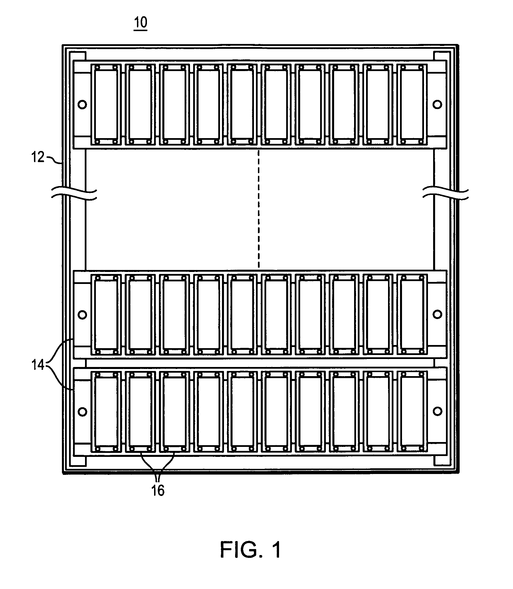
[0020]Referring to FIG. 1, there is shown an example of a rack mount system 10 in which the present invention can be employed. A rack mount cabinet 12 includes several storage systems 14. Each storage system 14 has installed therein several disk drives 16.

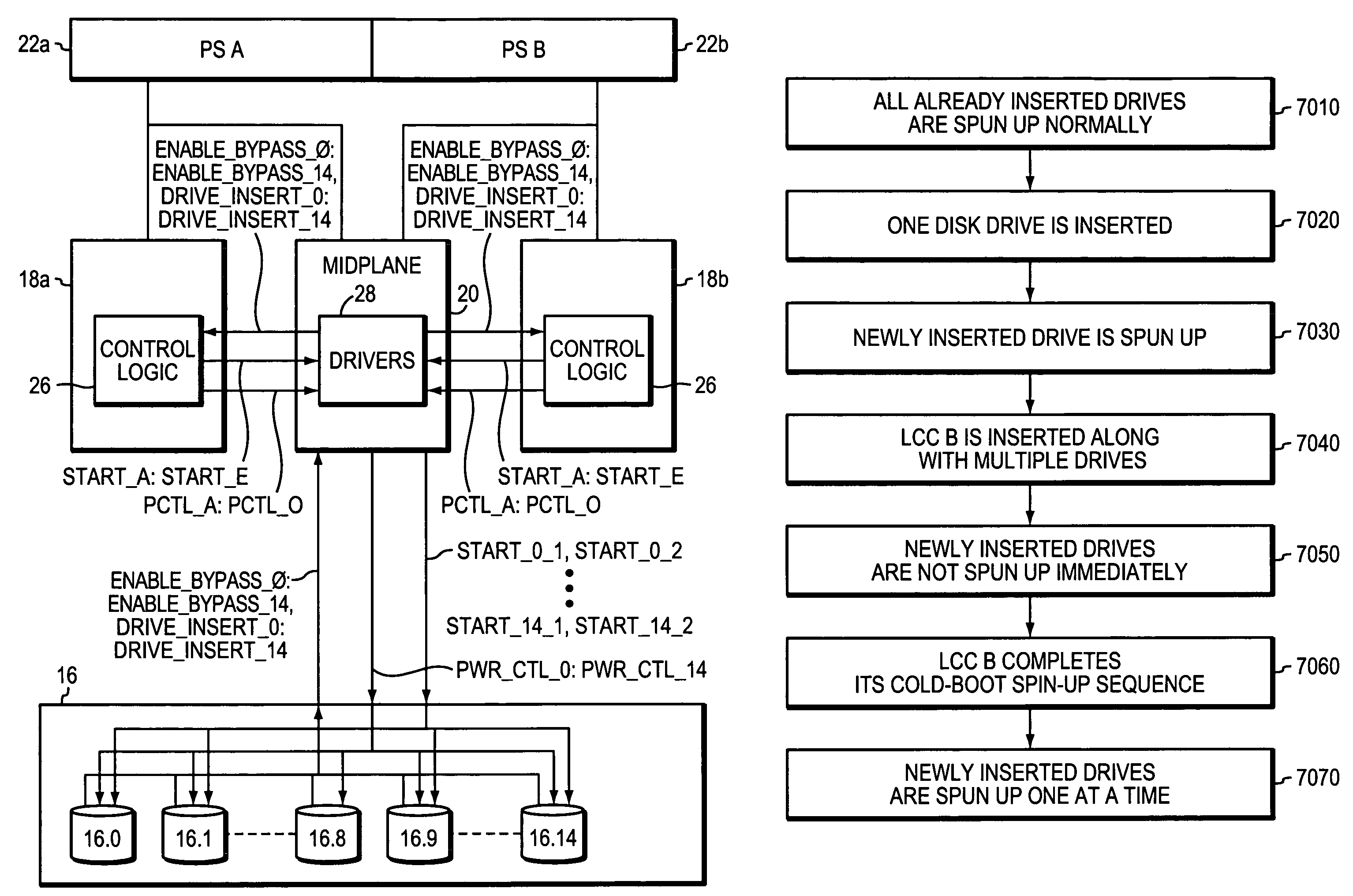
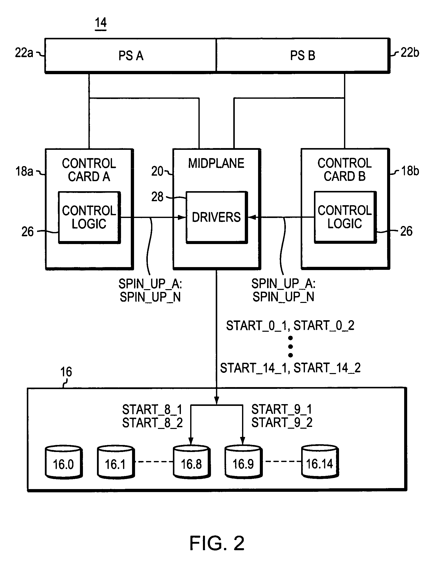
[0021]The amount of storage in the multi-chassis system can be increased by adding new storage systems 14 to the rack mount system 10, and by adding more disk drives 16 to one or more of the storage systems 14. A functional block diagram of one of the storage systems 14 is shown in FIG. 2. The storage system 14 includes two redundant link control cards (LCCs) 18a and 18b to provide high availability of the system. The LCCs 18a,b are coupled to a midplane 20. Disk drives 16, herein shown as 15 disk drives 16.0-16.14, are also coupled to the midplane 20.

[0022]Each LCC 18a,b communicates with all the drives 16.0-16.14 via the midplane 20. Power is supplied to the LCCs 18a,b, the midplane 20, and the disk 10 drives 16 by a redundant se...


PUM


Abstract

Apparatus for use in managing disk drive spinup includes a plurality of disk drives newly inserted into a data storage system enclosure that is in an already powered up steady state. The apparatus also includes first and second control cards in the enclosure, and first control logic operable to cause the first and second control cards to coordinate to cause the disk drives to spin up in stages.

Description

RELATED APPLICATION[0001]This application is a continuation-in-part application claiming priority to U.S. patent application Ser. No. 11 / 094,024, filed Mar. 30, 2005 now U.S. Pat. No. 7,173,787, reference nos. EMC-05-033 and 130-047, entitled “Apparatus and Method for Controlling Disk Drive Spin Up” (“'024 application”), the entirety of which patent application is incorporated by reference herein.FIELD OF THE INVENTION[0002]The present invention relates generally to the field of storage systems, and particularly to mechanisms for managing disk drive spin up in a storage system that supports many disk drives.BACKGROUND OF THE INVENTION[0003]The need for high performance, high capacity information technology systems is driven by several factors. In many industries, critical information technology applications require outstanding levels of service. At the same time, the world is experiencing an information explosion as more and more users demand timely access to a huge and steadily gro...

Claims


Application Information

Patent Timeline
IPC IPC(8): G11B15/18
CPCG11B19/209
Inventor SARDELLA, STEVEN D.SHUBEL, PAUL ANTON
Owner EMC IP HLDG CO LLC
Why Eureka
Try Eureka