
Cover for pockets in precast concrete panels

a precast concrete and pocket technology, applied in the field of precast concrete pocket covers, can solve the problems of not being able to easily bond paint, easy to fall out of or be easily removed from the pocket, and affecting the appearance of the building, etc., to achieve excellent adhesion and adhesion, strong and flexible, and easy to install and manufacture.

Active Publication Date: 2008-10-28
MEADOW BURKE
View PDF36 Cites 30 Cited by
  • Summary
  • Abstract
  • Description
  • Claims
  • Application Information

AI Technical Summary

Benefits of technology

[0016]A preferred embodiment of the cover comprises two projecting members. However, the cover may comprise any suitable number of projecting members based on the size of the open pocket to be concealed. The two projecting members are operatively positioned in a spaced relationship to each other. The spacing is preferably such so as to allow an exposed anchor in the pocket to be positioned between the two projecting members and, thus, provide a balanced fit.
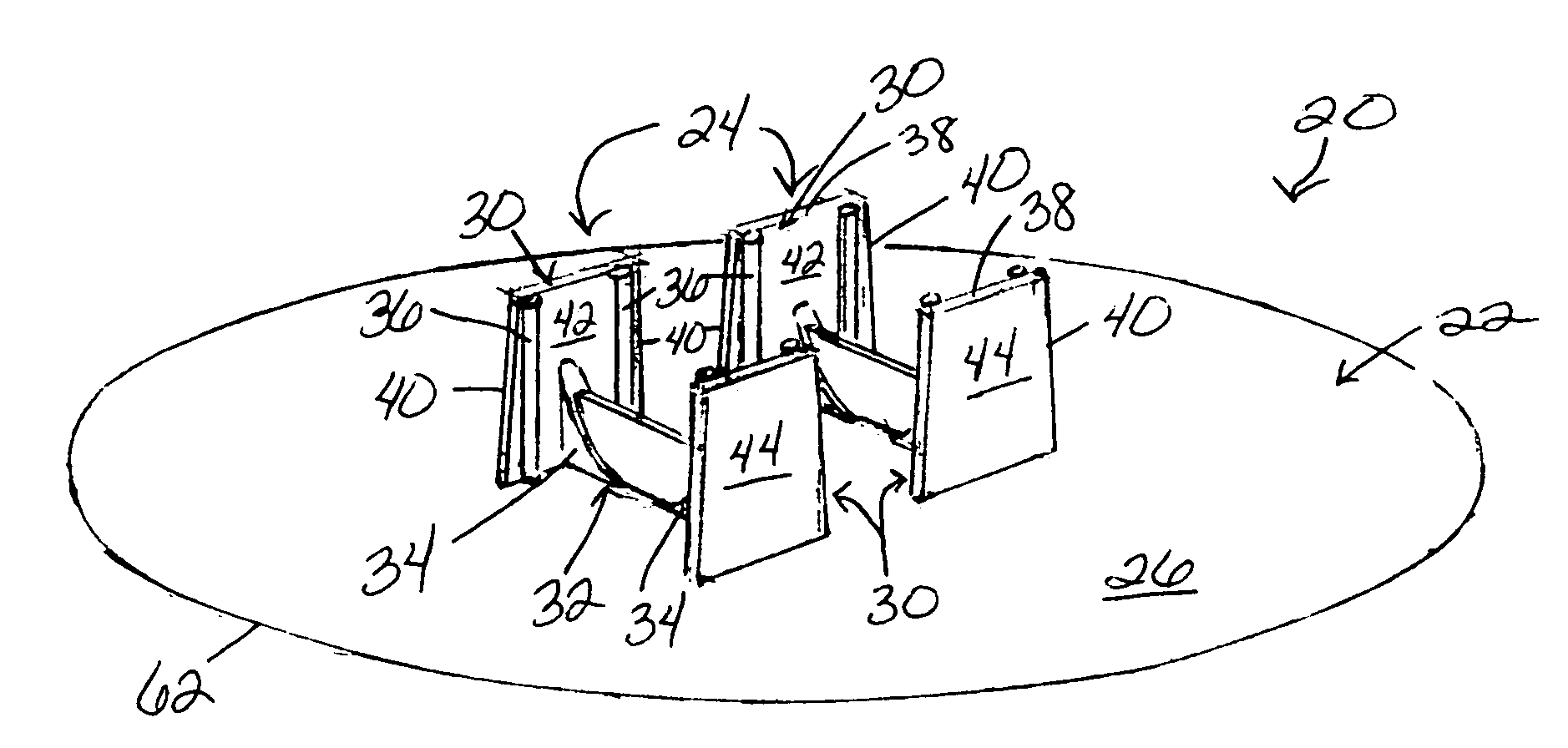
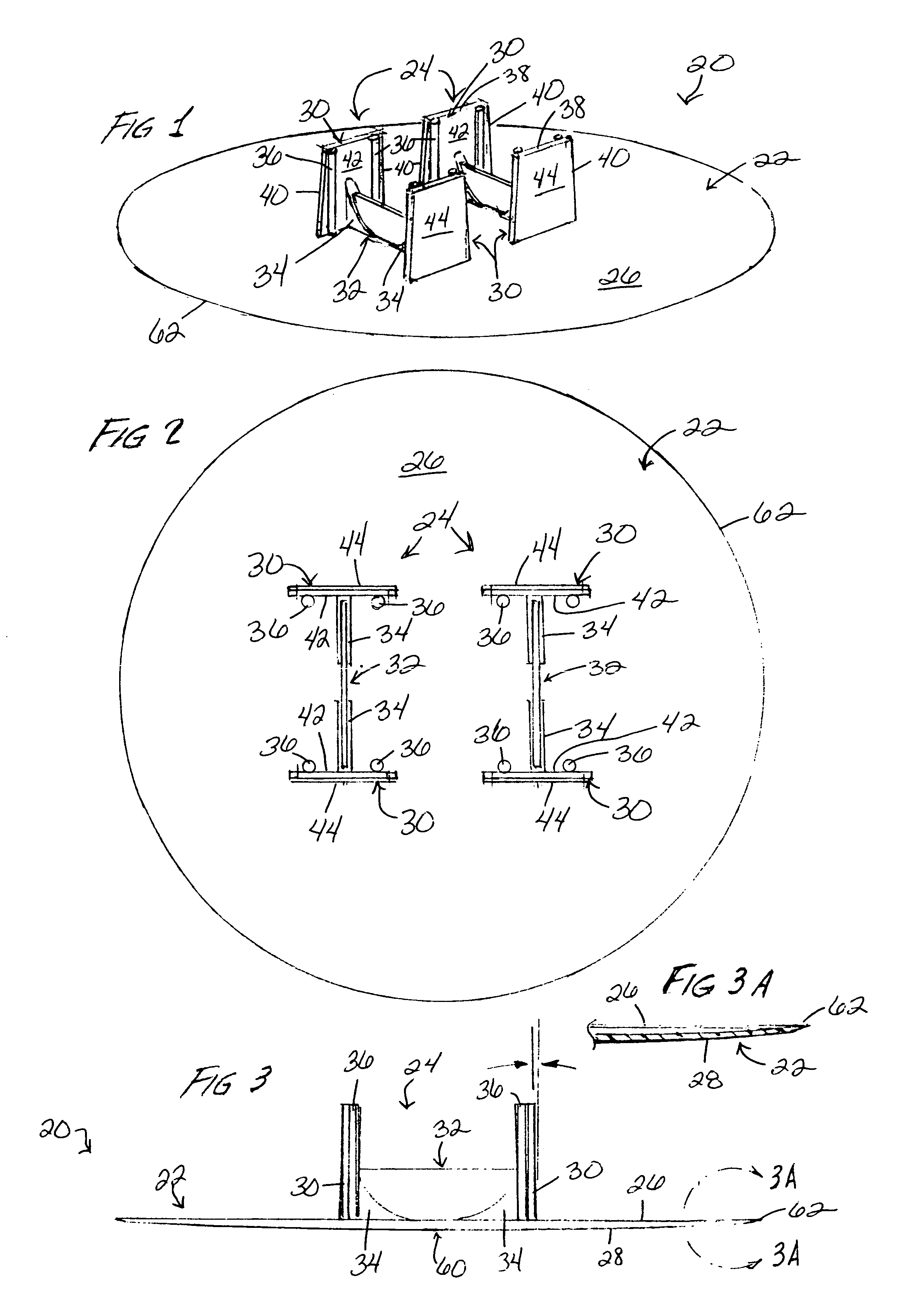
[0017]Each projecting member has two opposed end walls, i.e., a first end wall and a second end wall, joined by a cross wall or rib having a lesser height than the height of the end walls. The end walls of the projecting members direct insertion of the cover into an open pocket in a precast concrete panel and abut the interior walls of the pocket. The upper portion of the projecting members are flexible to allow the projecting members to conform to the draft or taper of the pocket walls. The cross wall provides support to the end walls and is under compression in use, thereby providing the end walls with support for maintaining position of the projecting members, and thus cover, in the open pocket in the precast concrete panel. The end walls are preferably slightly tapered inward from the base to the top end of each wall. This provides for a tighter fit once the cap is in place for use.
[0018]The cover is made of plastic, preferably acrylonitrile butadiene styrene (ABS) and formed by molding. The compressive stress of ABS is approximately at least twice that of its flexural strength. ABS also provides for good adhesion to paint thereto which allows for improving the aesthetic appearance of the cover once in place in a wall. Since the side walls of the pocket are made by a molded plastic part, the side walls are very predictable and usually vary in an amount of within about 0.01 to 2.5 mm. The location of the exposed anchor, however, can vary up to about ¾″ due to variation in position. Since the cover of the invention does not attach to the exposed anchor, the position of the anchor within the pocket is inconsequential.
[0020]The cover allows insertion thereof into an open pocket, recess or the like in a precast concrete panel and retains its strength and position within the open pocket and is not subject to stress relaxation due to the cross wall being under compression.
[0021]Further, the cover is strong, flexible and easy to install and manufacture as well as made of a material which has excellent properties for the adhesion of paint thereto.

Problems solved by technology

However, this can be messy and difficult since the panels are in a vertical orientation once assembled and the fill material tends to flow out of the pocket or requires a second coat due to shrinkage on the first fill.
However, known covers have various shortcomings including being ill-fitting, and being prone to warping and relaxing under flexural stress by the material of the cover, whereby the cover then becomes loose in the pocket and can easily fall out of or be easily removed from the pocket.
Many of these known covers are also constructed of a material that is weak, relaxes under pressure and does not allow paint to easily bond thereto.
These known devices all have various shortcomings including being ill-fitting in a pocket, are prone to warping, prone to loss of strength under stress, easily removed from a recess in a precast concrete panel and poor adhesion of paint thereto.

Method used


Image

  • Cover for pockets in precast concrete panels
  • Cover for pockets in precast concrete panels
  • Cover for pockets in precast concrete panels

Examples


Embodiment Construction

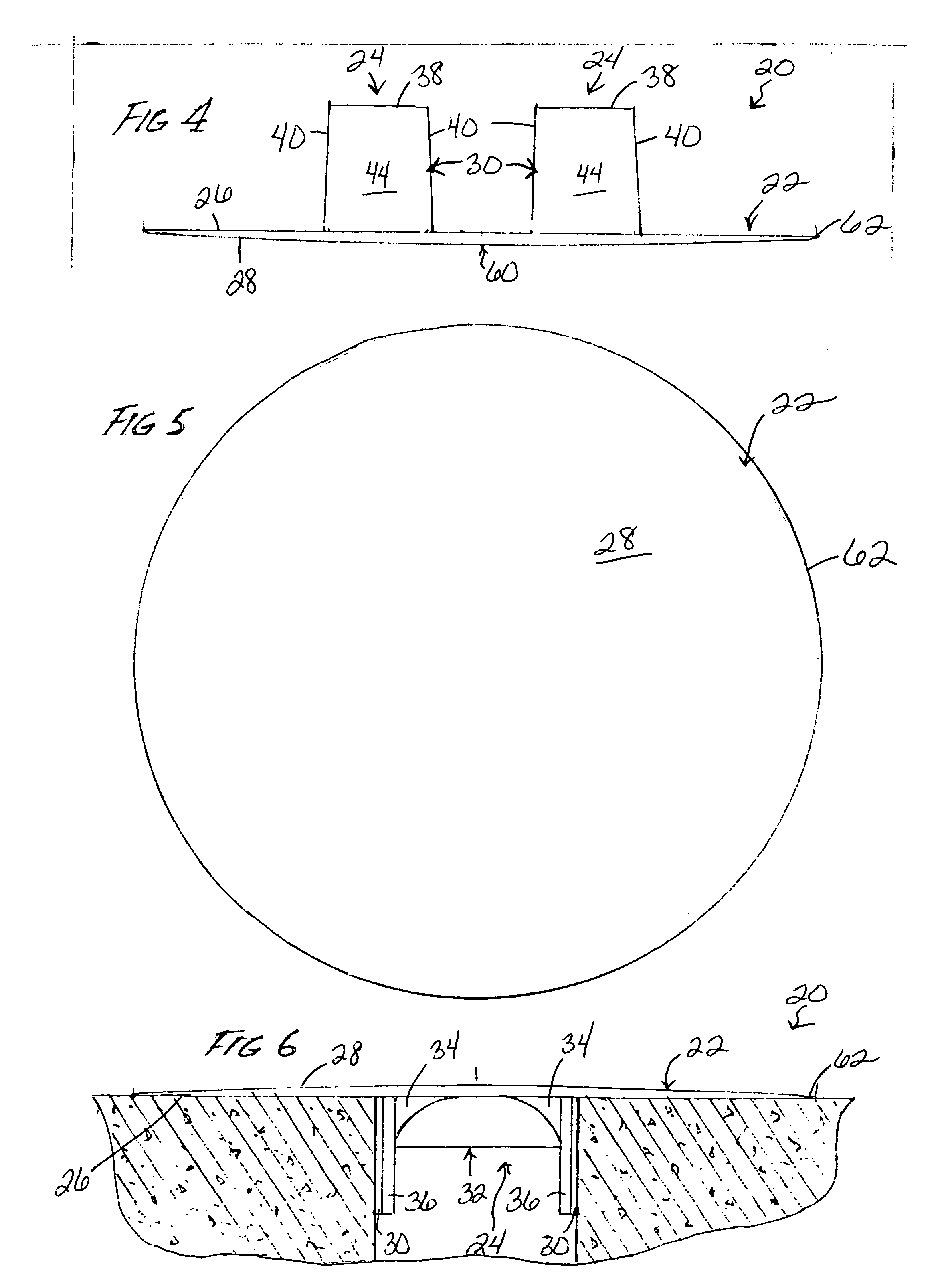
[0033]The invention concerns a cover 20 for concealing an open pocket, recess or the like present in a precast concrete panel following removal of a form for positioning an anchor in the precast concrete panel. The cover 20 maintains its flexural strength and position due to being under compression while in position in the open pocket in the precast concrete panel due to its structure.

[0034]Referring to FIGS. 1-7, cover 20 comprises a planar or flat or substantially planar or flat top portion 22 sized to conceal an open pocket in a precast concrete panel. The top portion 22 has an underside 26, an outer side 28 and a peripheral edge 62. The top portion 22 is preferably disk-shaped. The cover 20 also comprises at least one projecting member 24, and more preferably two projecting members 24, extending outward from the underside 26 of the top portion 22. While the cover 20 preferably comprises two projecting members 24, the cover 20 may comprise any suitable number of projecting member...


PUM


Abstract

A cover for concealing an open pocket, recess or the like in a precast concrete panel following removal of a form used for positioning an anchor in the concrete panel during manufacture thereof is disclosed. The cover includes a planar or flat or substantially planar or flat top sized to cover an open pocket in a precast concrete panel, and at least one projecting member extending outward from an underside of the top of the cover. Each projecting member has two opposed end walls joined by a cross wall having a lesser height than the height of the end walls. The cross wall is positioned operatively substantially perpendicular to the two end walls of the projecting member and is operatively connected to the end walls of the projecting member. The cross wall is under compression in use and supports the end walls which have sufficient flexibility to conform to the side walls of the pocket when positioned in the pocket. In use, the cover is unconnected to any exposed anchor or other structure present in the pocket.

Description

FIELD OF INVENTION[0001]The present invention relates to a cover for concealing outwardly open pockets or the like in precast concrete panels. More particularly, the invention relates to a cover for concealing an outwardly open pocket or the like in a precast concrete panel which maintains its flexural and compressive strength in use positioned in the pocket in the precast concrete panel.BACKGROUND OF INVENTION[0002]Many buildings are constructed of concrete panels which are precast and then assembled. In the precast manufacturing process, the concrete panels are normally cast flat in a mold, lifted from the mold and transported, usually in a horizontal orientation, and then assembled at a construction site.[0003]In lifting the precast panels to transport, position and assemble the panels, the concrete panels are handled by external hoist or lift devices which engage anchors preset in the precast panels during manufacture of the panels. With reference to FIG. 9, an anchor A (usually...

Claims


Application Information

Patent Timeline
Patent Type & Authority Patents(United States)
IPC IPC(8): E02D35/00
CPCE04B1/4142E04G15/04
Inventor LANG, FRANK J.
Owner MEADOW BURKE
Learn More