Gas turbine engine including stator vanes having variable camber and stagger configurations at different circumferential positions

a technology of stator vanes and gas turbine engines, which is applied in the direction of machines/engines, liquid fuel engines, combustion air/fuel air treatment, etc., can solve the problems of aerodynamic loss, the input effect of the propulsive fan of the gas turbine engine may be further compromised, and the inability to achieve the effect of reducing the aerodynamic loss

Active Publication Date: 2008-11-04
ROLLS ROYCE PLC
View PDF19 Cites 65 Cited by
  • Summary
  • Abstract
  • Description
  • Claims
  • Application Information

AI Technical Summary

Benefits of technology

[0007]In accordance with the present invention there is provided a gas turbine engine comprising an intake, a low pressure compressor including a plurality of rotor blades arranged downstream of the intake, a plurality of stator vanes arranged downstream of the low pressure compressor and at least one obstruction arranged downstream of the stator vanes, whereby in use the at least one obstruction producing a circumferentially varying back pressure on the stator vanes and the intake supplying an airflow having a circumferentially varying forward flow pressure to the low pressure compressor due to a non-axisymmetric flow of air into the intake, the stator vanes are arranged to balance the circumferentially varying back pressure from the at least one obstruction with the circumferentially varying forward flow pressure from the intake at substantially all circumferential positions.

Problems solved by technology

Particular problems occur with regard to the propulsive fan of the gas turbine engine.
Unfortunately, as a result of several factors, there are problems associated with this basic relationship.
Firstly, due to the nature of attaching a gas turbine engine to an aircraft wing, there is a so-called droop phenomena whereby the airflow is not presented parallel to the engine axis.
This input effect upon presentation of the air flow to the air intake may be further compromised by side winds etc.
Further problems relate to aerodynamic losses as a result of fan blade tip vortex phenomena and other factors.
It will also be understood that there is a significant problem with respect to so-called fan forcing which is as a result of circumferential pressure variations around the air intake of the gas turbine engine such that each fan blade must force its way between these variations and this in turn causes stress to the fan blades.
A further problem relates to the necessity to mount the gas turbine engine with a substantial mounting pylon just to the rear of the stator vanes and also provision of radial drive struts at similar positions.
This detailed analysis is complicated due to the high number of possible variables such that previously, modelling has been limited to the angular laminar flow presented by rotation of the airflow aerofoil blades of the fan to the stator vanes given particular pylon and / or radial drive strut configurations.
In such circumstances, the most significant problem is that relating to fan forcing, the stator vanes positions have been optimised in order to minimise that problem such that droop / crosswinds have been neglected and such as other efficiency reducing problems aerodynamic losses and buffet flutter have been accepted as inherent operational consequences.

Method used


Image

  • Gas turbine engine including stator vanes having variable camber and stagger configurations at different circumferential positions
  • Gas turbine engine including stator vanes having variable camber and stagger configurations at different circumferential positions
  • Gas turbine engine including stator vanes having variable camber and stagger configurations at different circumferential positions

Examples


Embodiment Construction

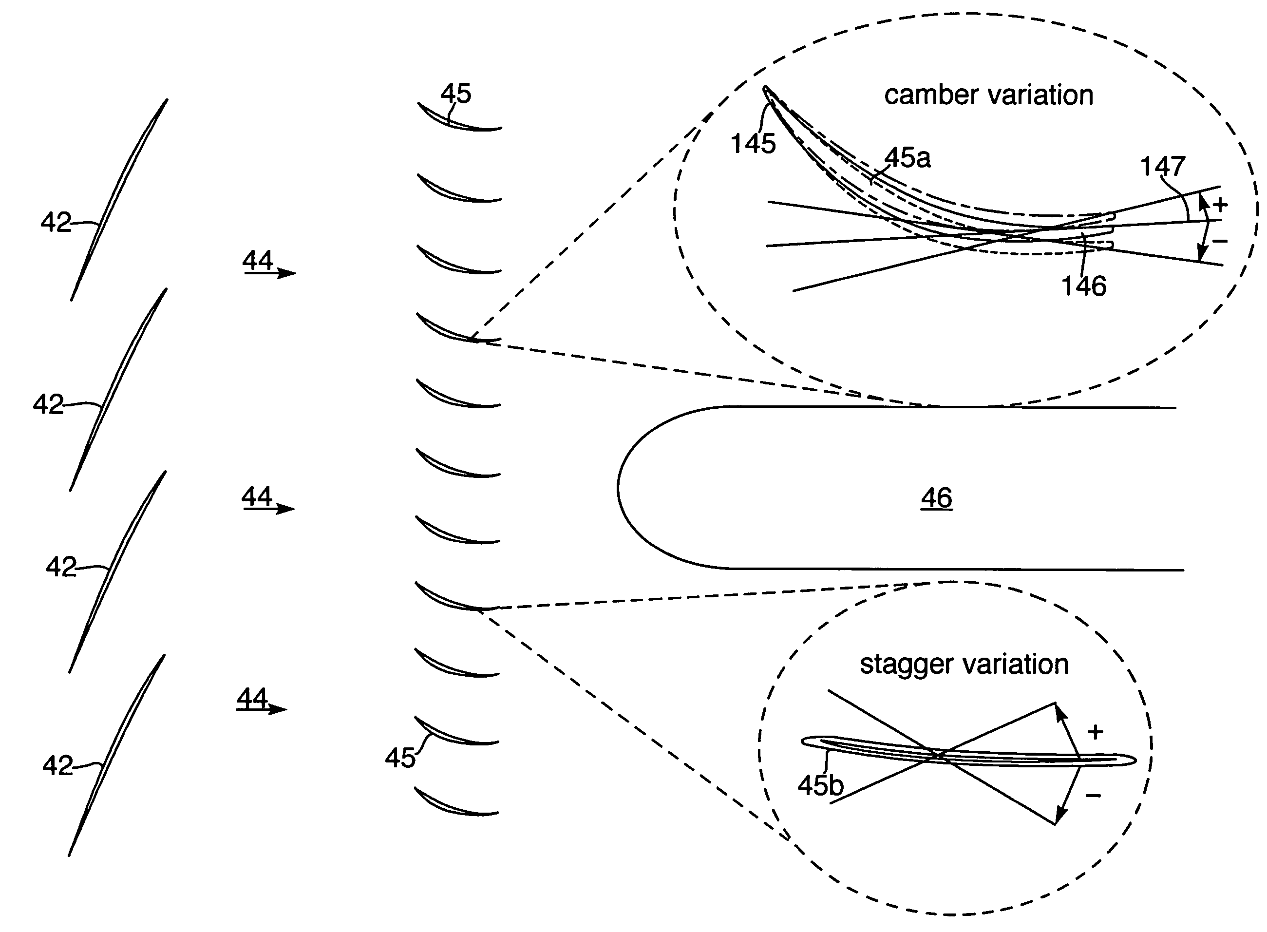
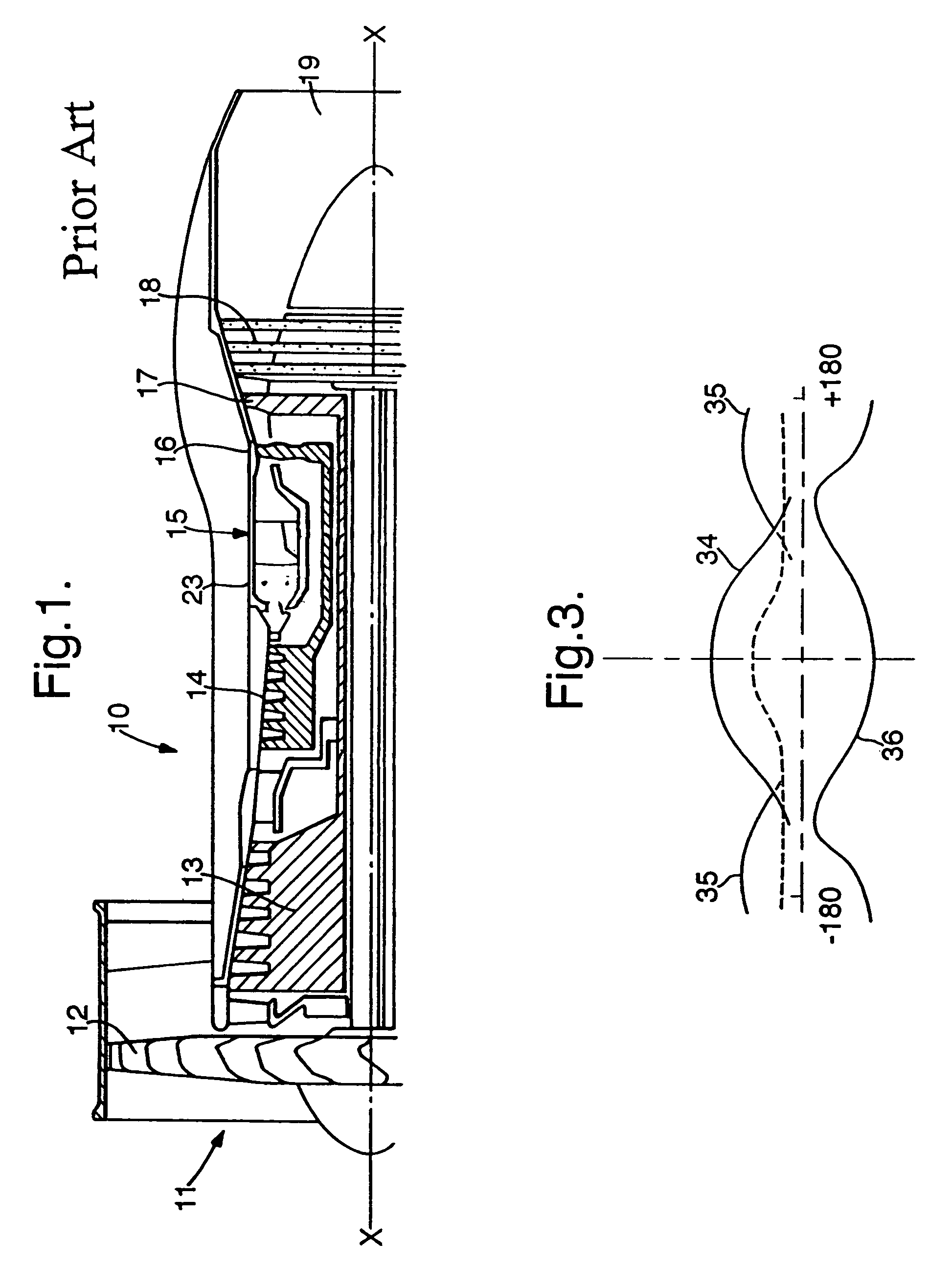
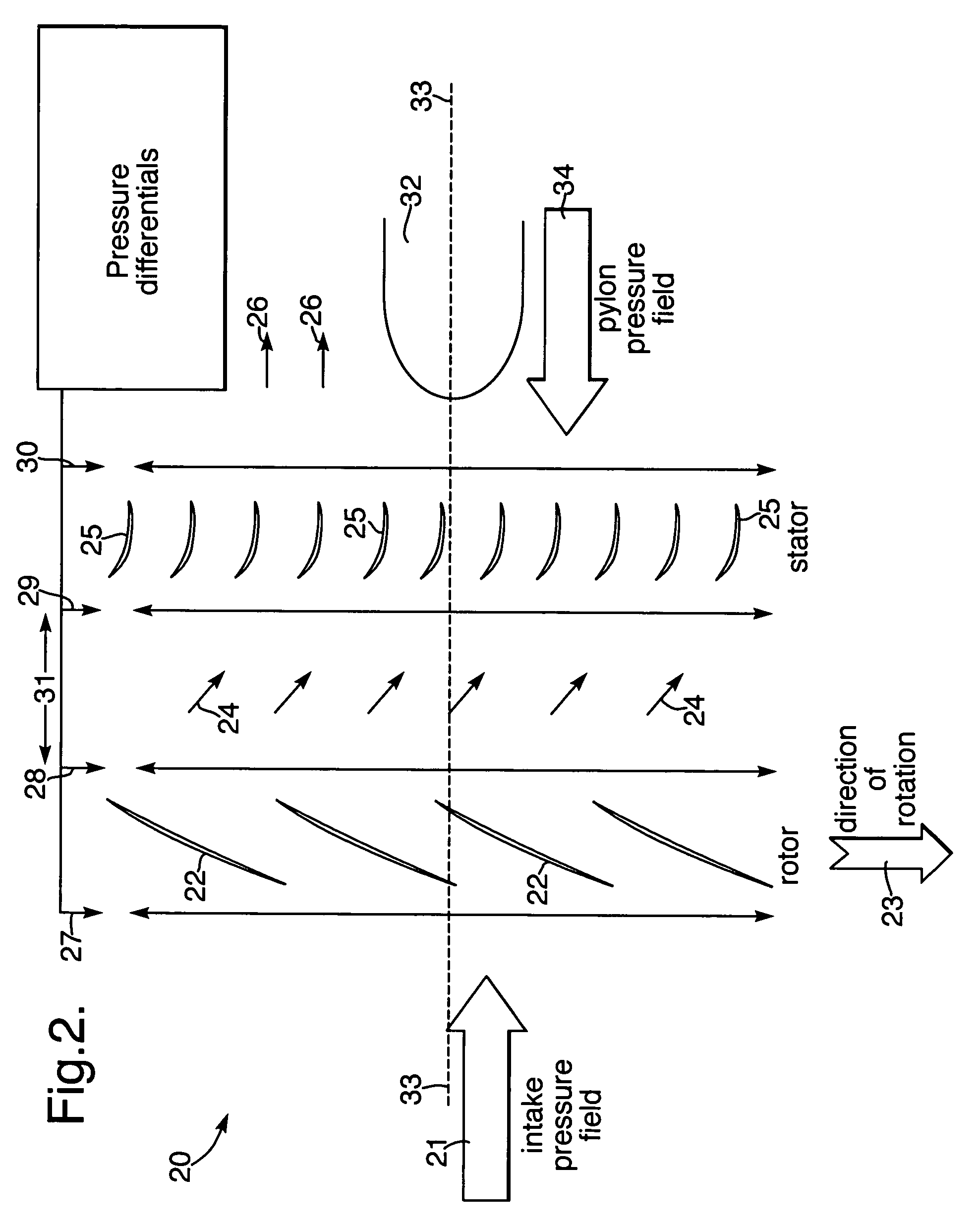
[0021]The present invention relates to the design of an air intake for a gas turbine engine. This air intake is a low pressure compression system for an axial flow compressor in the engine. The low pressure compression system comprises the intake to the fan or compressor, the fan or compressor, the outlet guide vanes or stator vanes on the stator and any obstructions such as pylons used to support the engine upon an aircraft wing or struts used to enclose radial drives or other features which cause an upstream variation in pressure for example bleed ducts. As indicated above, there is an associated non-axisymmetric flow to the intake caused usually by droop in the airflow to the intake. It is also understood that non-axisymmetric flow in the low pressure system of a gas turbine engine generates a number of undesirable features. For example, at certain circumferential locations, there are localised regions of high Mach number flow on the stator vanes and localised regions of high sta...


PUM


Abstract

Within an intake for a gas turbine engine provision is provided through stator vanes 25, 45 in the stator whereby back pressure from a necessary obstruction 34, 46 can be utilised to balance forward pressure variations caused by intake droop or crosswinds in order to reduce those forward pressure detriments for more efficient engine operation according to a desired objective regime. Typically the flow through the intake 20 is analysed and then an appropriate positioning of the stator vanes 25, 45 determined in order to provide approximate balance between the forward pressures and back pressures. Normally, a combination of camber variation of stator vanes 45a and stagger variation of stator vanes 45b are utilised in order to achieve a desired momentum balance around the circumference of the intake 20. It will be understood that both the forward pressures and the back pressures are differentially variable about the circumference such that one opposes the other.

Description

FIELD OF THE INVENTION[0001]The present invention relates to gas turbine engines and more particularly to fan arrangements to provide more efficient airflow.BACKGROUND OF THE INVENTION[0002]Referring to FIG. 1, a gas turbine engine is generally indicated at 10 and comprises, in axial flow series, an air intake 11, a propulsive fan 12, an intermediate pressure compressor 13, a high pressure compressor 14, a combustor 15, a turbine arrangement comprising a high pressure turbine 16, an intermediate pressure turbine 17 and a low pressure turbine 18, and an exhaust nozzle 19.[0003]The gas turbine engine 10 operates in a conventional manner so that air entering the intake 11 is accelerated by the fan 12 which produce two air flows: a first air flow into the intermediate pressure compressor 13 and a second air flow which provides propulsive thrust. The intermediate pressure compressor 13 compresses the air flow directed into it before delivering that air to the high pressure compressor 14 ...

Claims


Application Information

Patent Timeline
Patent Type & Authority Patents(United States)
IPC IPC(8): F02K3/02F01D5/10F01D5/14F01D9/04F02C7/00F02C7/04F04D29/54
CPCF01D5/10F01D5/142F01D9/041F02C7/00F02C7/04F04D29/542Y02T50/671Y02T50/673F04D29/544Y02T50/60F04D19/00F04D29/541
Inventor PARRY, ANTHONY B
Owner ROLLS ROYCE PLC
Why Eureka
Try Eureka