
Method and apparatus for washing objects

a technology for washing objects and objects, applied in the direction of cleaning processes and apparatus, lighting and heating apparatus, and using liquids to clean, etc., can solve the problems of reducing affecting the efficiency of the blade, and affecting the effectiveness of the blad

Active Publication Date: 2008-11-04
ECOSERVICES
View PDF35 Cites 75 Cited by
  • Summary
  • Abstract
  • Description
  • Claims
  • Application Information

AI Technical Summary

Benefits of technology

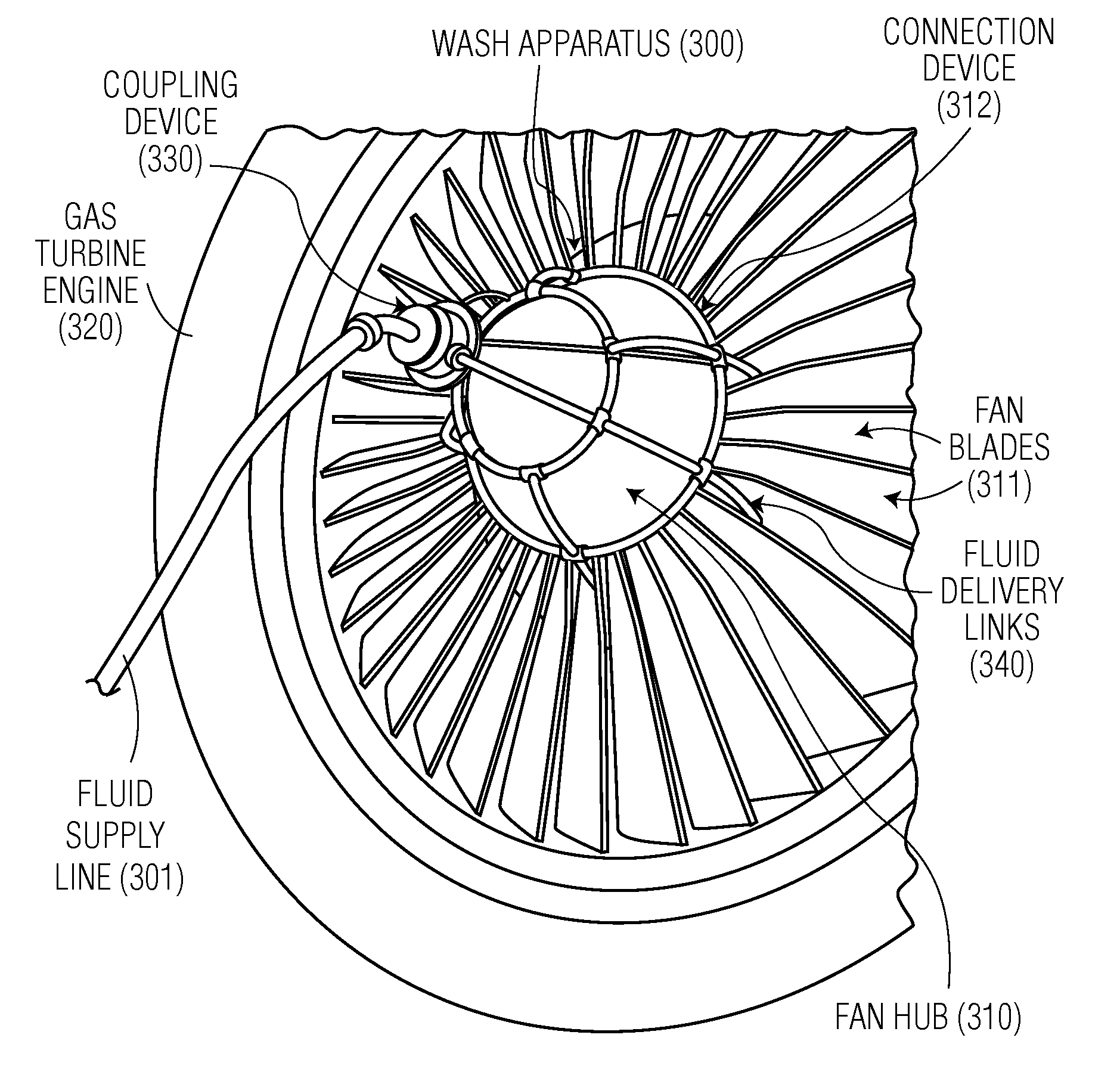
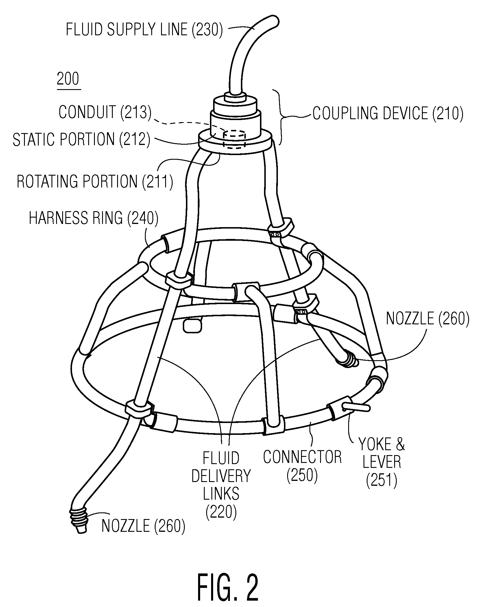
"The present invention is about methods, systems, and apparatus for cleaning objects, such as gas turbine engines. The invention includes a mobile harness assembly that can be connected to the engine's fan hub for delivering washing fluid directly into the engine's core while it is cranked. The harness assembly includes a coupling device that connects fluid supply lines to fluid delivery lines, which remain static relative to the rotating fan hub. The harness assembly also includes one or more harness rings for positioning and stabilizing the fluid delivery lines relative to the fan blades, and a connector for removably attaching the harness assembly to the fan hub. The invention allows for efficient cleaning of gas turbine engines by delivering washing fluid directly to the engine core while it is cranked."

Problems solved by technology

Certain objects, including without limitation, gas turbine engines, routinely become soiled and coated by air-borne contaminants that enter and adhere themselves to such objects.
In the case of a gas turbine engine, these contaminants or fouling typically enter the engine and adhere themselves to the engine fan and compressor blades.
These contaminants eventually accumulate on the compressor blades, resulting in a decrease in the effectiveness of the blades in a manner that reduces total air flow and total produced power from the gas turbine engine.
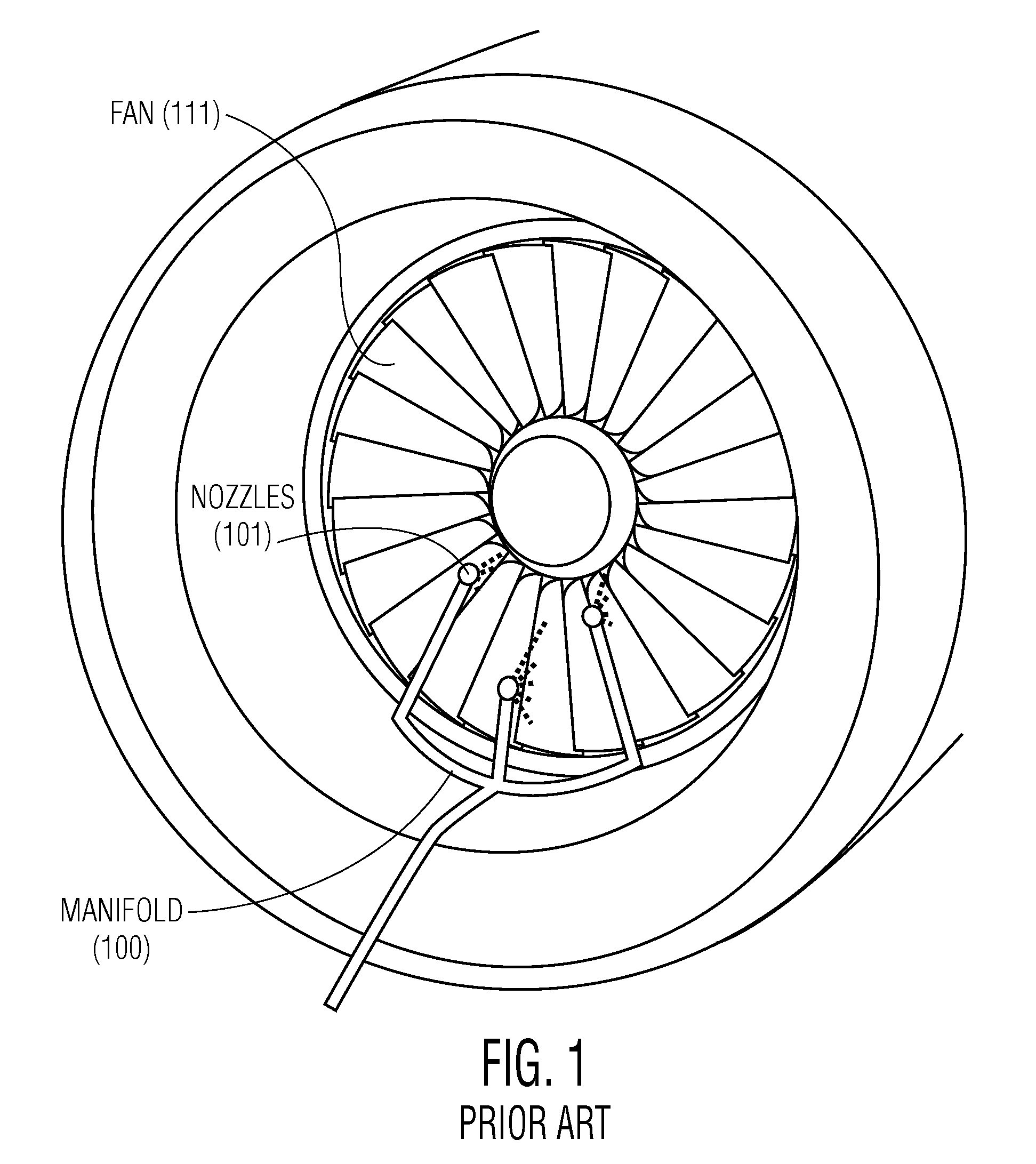
Utilizing such methods and equipment, however, is ineffective for removing contaminants that have accumulated downstream of the fan (111).
As a result, much of the wash fluid's velocity and volume will be lost before the wash fluid reaches the downstream components.
As a result, the cost and time required to complete such a washing procedure are increased.

Method used


Image

  • Method and apparatus for washing objects
  • Method and apparatus for washing objects
  • Method and apparatus for washing objects

Examples


Embodiment Construction

[0016]Disclosed herein are methods and apparatus relating to a mobile wash unit for use in washing objects such as gas turbine engines and / or similar objects. In an exemplary embodiment, the present invention relates to methods and apparatus for injecting uninterrupted stream(s) of wash fluid directly into a gas turbine engine core as the engine is cranked. To that end, the present invention provides a mobile wash unit adapted for cleaning one or multiple engines at the same time, or alternatively in any desired sequence. For this purpose, the mobile wash unit includes one or more units that are each configured for direct mounting onto a fan-hub portion of the engine's fan. Where multiple units would be provided, each unit would be directly mounted onto the fan-hub portion of a different engine. Fluid dispensed from the mobile wash unit is directed to flow between the fan's blades and directly into the engine core. Since the mobile wash unit is mounted directly onto the fan hub, a p...


PUM


Abstract

A wash apparatus includes a harness assembly comprising a coupling device a coupling device for connecting one or more fluid supply lines to one or more fluid delivery lines; one or more fluid delivery lines removably attached at one end to the coupling device's first portion and positioned for delivering washing fluid directly into the gas turbine engine core as the engine is cranked; one or more fluid supply lines removably attached to the coupling device's second portion for supplying washing fluid to the harness assembly and remaining in a static position relative to the rotating fluid delivery lines; one or more harness rings attached to the one or more fluid delivery lines for spacing, stabilizing, and positioning the fluid delivery lines relative to the fan blades; and a connector for removably attaching the harness assembly directly onto the fan hub.

Description

FIELD OF THE INVENTION[0001]The present invention relates generally to methods and apparatus for washing objects. More particularly, the present invention describes methods and apparatus for effectively and efficiently washing objects, including rotating objects such as gas turbine engines, by delivering washing fluid directly into the object being washed.BACKGROUND[0002]Certain objects, including without limitation, gas turbine engines, routinely become soiled and coated by air-borne contaminants that enter and adhere themselves to such objects. In the case of a gas turbine engine, these contaminants or fouling typically enter the engine and adhere themselves to the engine fan and compressor blades. These contaminants eventually accumulate on the compressor blades, resulting in a decrease in the effectiveness of the blades in a manner that reduces total air flow and total produced power from the gas turbine engine.[0003]One manner of preventing degradation and of reversing the adve...

Claims


Application Information

Patent Timeline
Patent Type & Authority Patents(United States)
IPC IPC(8): B08B7/00B08B3/12B08B7/04B08B9/00
CPCB08B3/02B08B9/00F01D25/002
Inventor ASPLUND, PETER
Owner ECOSERVICES
Learn More