
Method and apparatus for collecting pollutants in a body of water

a technology for collecting methods and pollutants, applied in water cleaning, filtration separation, separation processes, etc., can solve problems such as difficult to have a satisfactory control of affect the function in an unpredictable manner, and difficult to reliably control the intake and discharge phases in all operating situations

Inactive Publication Date: 2008-11-04
SURFCLEANER AB
View PDF13 Cites 8 Cited by
  • Summary
  • Abstract
  • Description
  • Claims
  • Application Information

AI Technical Summary

Benefits of technology

[0009]The problem to be solved by the invention is to provide a method of the kind indicated in which the initiation and termination of the intake and discharge phases can be controlled reliably in a satisfactory manner.

Problems solved by technology

Using conventional sensors it is difficult to control the intake and discharge phases reliably in a satisfactory manner.
If particles enter the region of the sensors, the function is affected in an unpredictable manner.
Other sensors which may be contemplated for the detection of the interfaces or density differences between the layer of pollutants and the water carrying the layer suffer from diverse problems which make it difficult to have a satisfactory control of the intake and the discharge in all operating situations.
A further problem is caused by the fact that the skimmed surface layer often contains material that has a higher density than the water of the surface layer but is nevertheless entrained by the surface layer and carried into the collection vessel.
In the collection vessel, however, this material may settle because of the low flow velocities which exist therein, especially in the separation compartment.
The settled material may collect on the bottom wall of the separation compartment and gradually load the collection vessel heavily enough to jeopardize the function of the skimmer apparatus.

Method used


Image

  • Method and apparatus for collecting pollutants in a body of water
  • Method and apparatus for collecting pollutants in a body of water
  • Method and apparatus for collecting pollutants in a body of water

Examples


Embodiment Construction

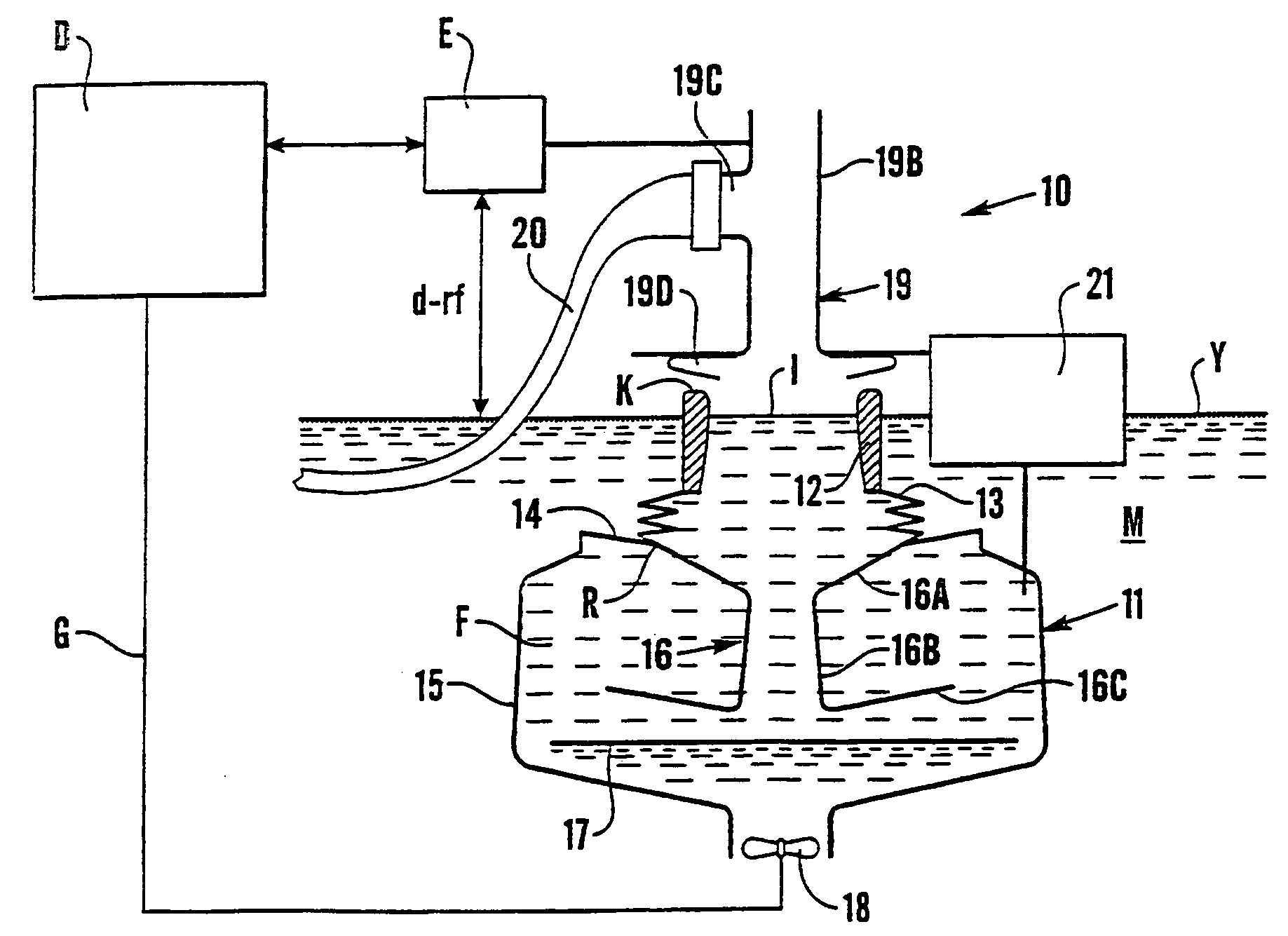
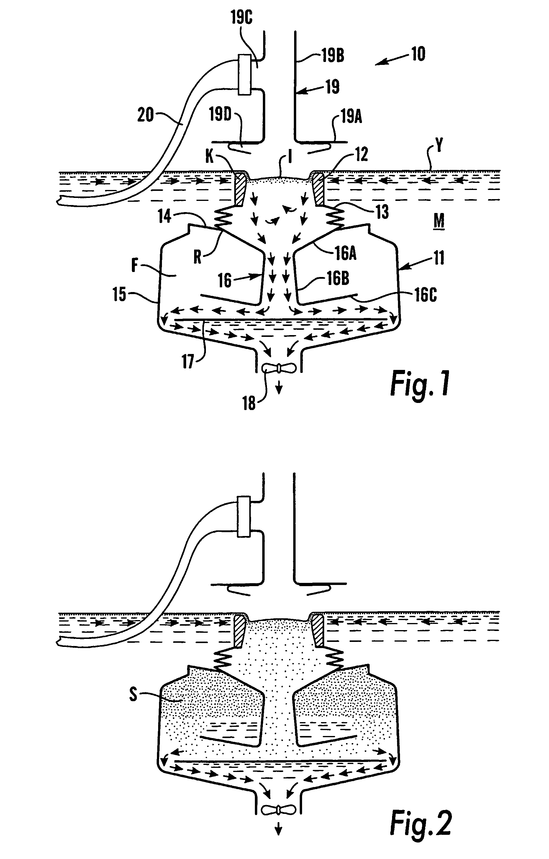
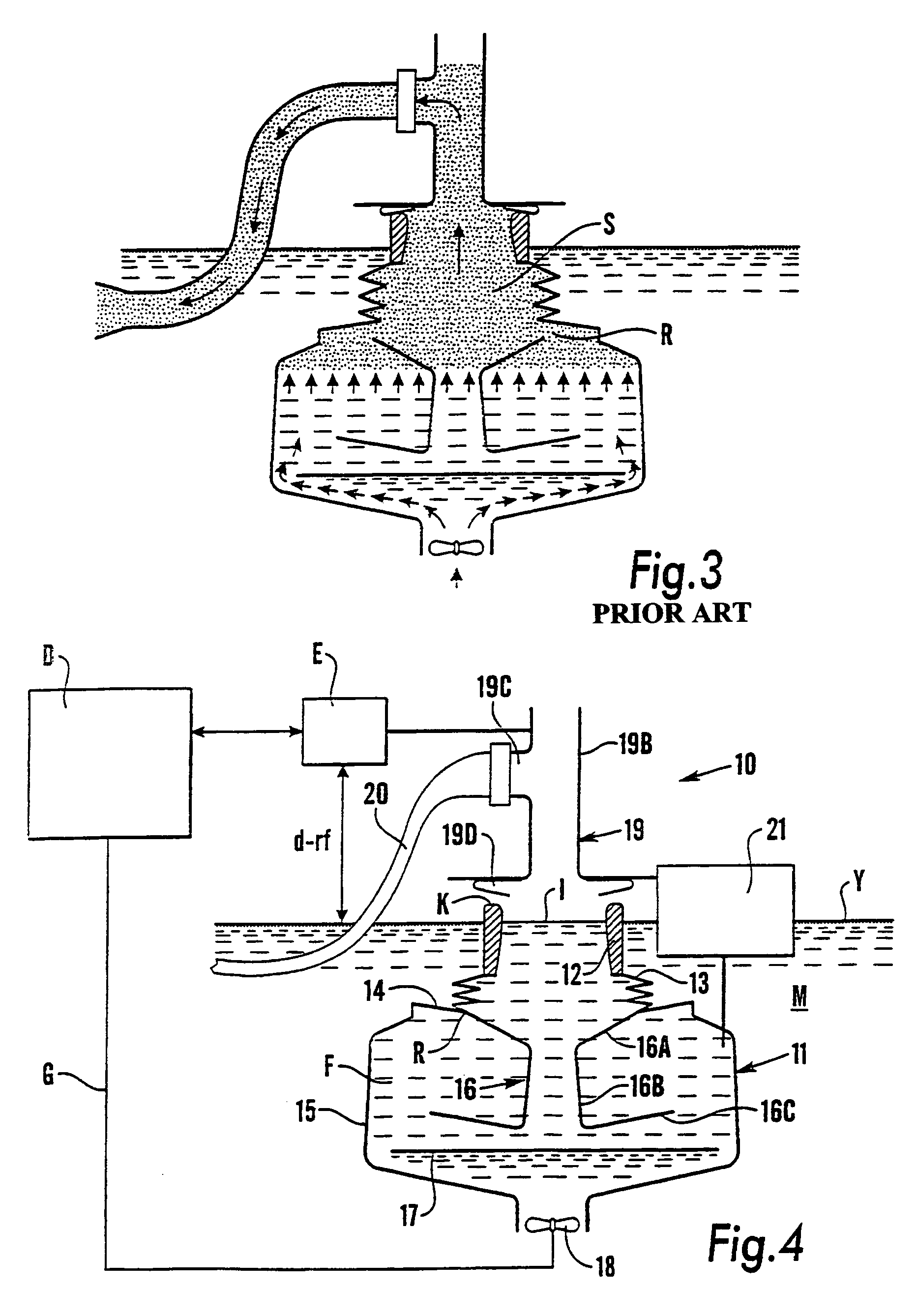
[0019]The skimmer apparatus 10 diagrammatically shown in FIGS. 1 to 3 is constructed substantially in accordance with WO01 / 12095 A1 and will be described here only to the extent necessary for the understanding of the present invention.

[0020]The skimmer apparatus 10 comprises a collection vessel 11, which is designed in operation to be immersed in the body of water M the surface layer Y of which carries the pollutants to be collected and disposed of with the aid of the skimmer apparatus.

[0021]An annular intake member 12 in the collection vessel 11 is formed by a buoyant ring the crest K of which defines an overflow inlet I and the lover side of which merges with or is attached to the upper end of an upstanding annular accordion-type bellows 13. At its lower end, this bellows is attached to the inner edge of an annular diaphragm disk 14, an outer edge of which is attached to the upper edge of a bowl-shaped, rigid container section 15.

[0022]An upstanding conduit element 16 is centrally...


PUM

PropertyMeasurementUnit
densityaaaaaaaaaa
weightaaaaaaaaaa
distanceaaaaaaaaaa

Abstract

During collection of pollutants having a density lower than that of water and carried by a surface layer of a body of water, water of the surface layer is caused to flow into and through a collection vessel having a separation compartment with a top wall, pollutants entrained by the inflowing surface layer water are allowed to collect gravimetrically as a supernatant layer carried beneath the top wall of the separation compartment on water in the separation compartment, and changes of the weight of the collection vessel in the body of water are monitored. Intake and discharge phases may be initiated and terminated to in response to the said weight reaching predetermined values.

Description

BACKGROUND OF THE INVENTIONPrior Art[0001]A known method for collecting pollutants having a density higher than that of water and carried by a surface layer of a body of water uses a skimmer apparatus, that is, an apparatus by which the surface layer of the body of water is skimmed off into a collection vessel. An example is shown in WO01 / 12905 A1.[0002]The method is cyclical with each cycle of operation comprising an intake phase and a discharge phase. During the intake phase, the surface layer runs into a collection vessel having a separation compartment with a top wall. The inflow into the collection vessel takes place through an inlet that communicates with the separation compartment. During the intake phase the pollutants entrained by the inflowing surface layer are allowed to collect gravimetrically, that is, by virtue of their lower density, to form a layer of pollutants beneath the top wall of the separation compartment. This layer floats on the underlying water in the separ...

Claims


Application Information

Patent Timeline
Patent Type & Authority Patents(United States)
IPC IPC(8): C02F1/40E02B15/04E02B15/10
CPCE02B15/106Y10S210/923
Inventor LUNDBACK, STIGJOHNSON, JONAS
Owner SURFCLEANER AB
Learn More