Information collection apparatus, information collection system, information collection method, program, and recording medium

a technology of information collection apparatus and information collection system, applied in the field of information collection apparatus, can solve the problems of limited battery downsizing, inability to select a predetermined sensor module and collect information about a predetermined position therefrom, and difficulty in downsizing the entire sensor module, so as to achieve the effect of not increasing power consumption power and data ra

Inactive Publication Date: 2008-11-04
CANON KK
View PDF6 Cites 54 Cited by
  • Summary
  • Abstract
  • Description
  • Claims
  • Application Information

AI Technical Summary

Benefits of technology

[0016]The present invention is directed to an information collection apparatus that can collect suitable information, based on photographing information, without increasing power consumption power and data rate, an information collection system incorporating the information collection apparatus, an information collection method, a program, and a recording medium.

Problems solved by technology

Therefore, it is impossible to select a predetermined sensor module and collect information about a predetermined position therefrom.
Although information about the predetermined position can be collected from each of the entire sensor modules, and unnecessary data can be selected and disposed of through an information collection apparatus, the above-described known systems have the following problems.
As a first problem, each of the sensor modules requires a relatively high-capacity battery mounted therein, so as to operate continuously over a long time period.
As such, there is a limit to battery downsizing, and therefore it is difficult to downsize the entire sensor module.
However, an adequate level of power-consumption reduction has not yet been attained.
Also problematic with the above-described known systems is that all the sensor modules transmit the measurement data with equal frequency.
Therefore, the method for collecting information transmitted from the sensors cannot be changed based on photographing information indicating the photographing direction or the like.
That is to say, the above-described system does not allow selecting a predetermined information-acquisition apparatus from among a plurality of information-acquisition apparatuses so as to collect information therefrom and control operations of the information-acquisition apparatuses.

Method used


Image

  • Information collection apparatus, information collection system, information collection method, program, and recording medium
  • Information collection apparatus, information collection system, information collection method, program, and recording medium
  • Information collection apparatus, information collection system, information collection method, program, and recording medium

Examples


first embodiment

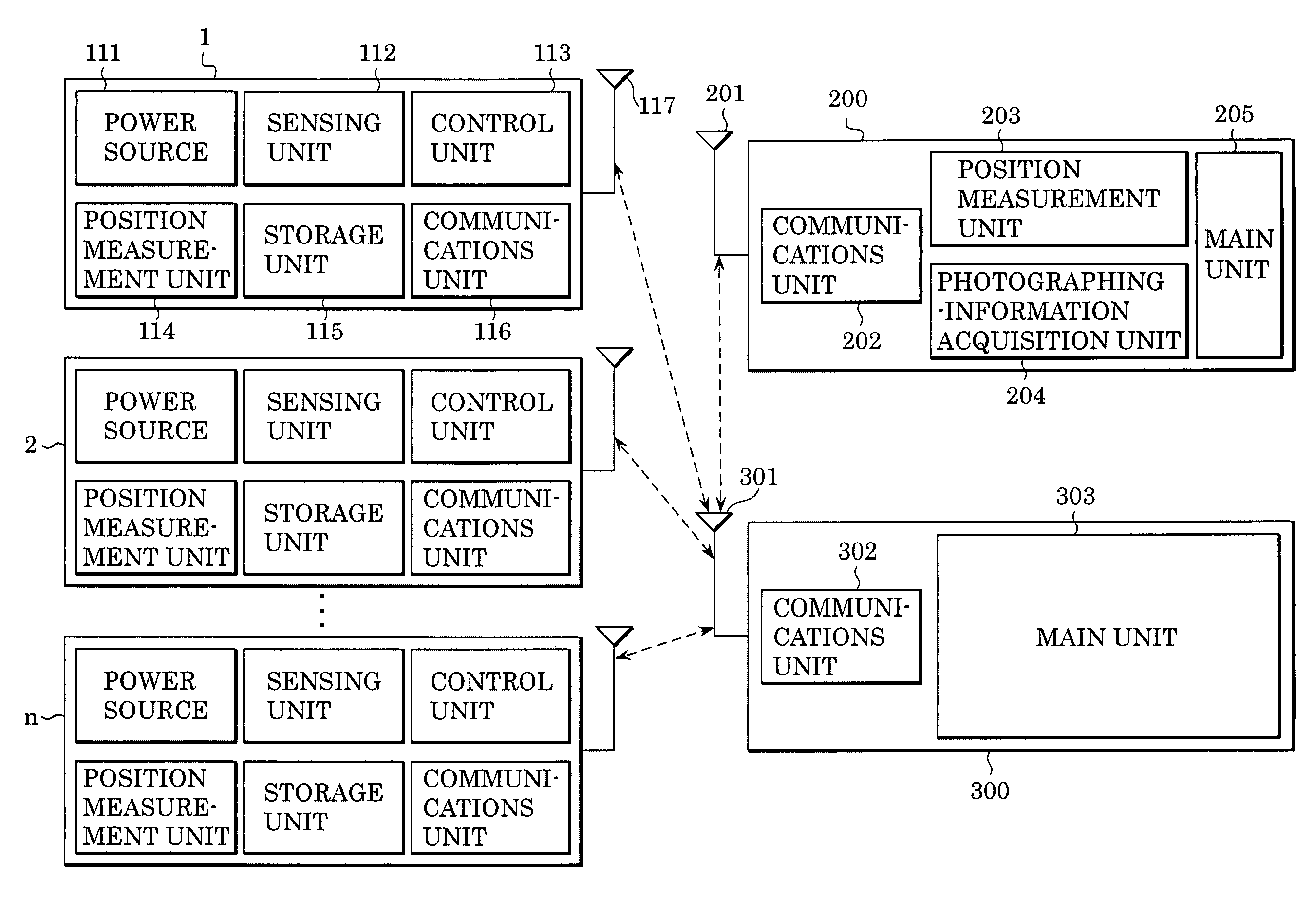
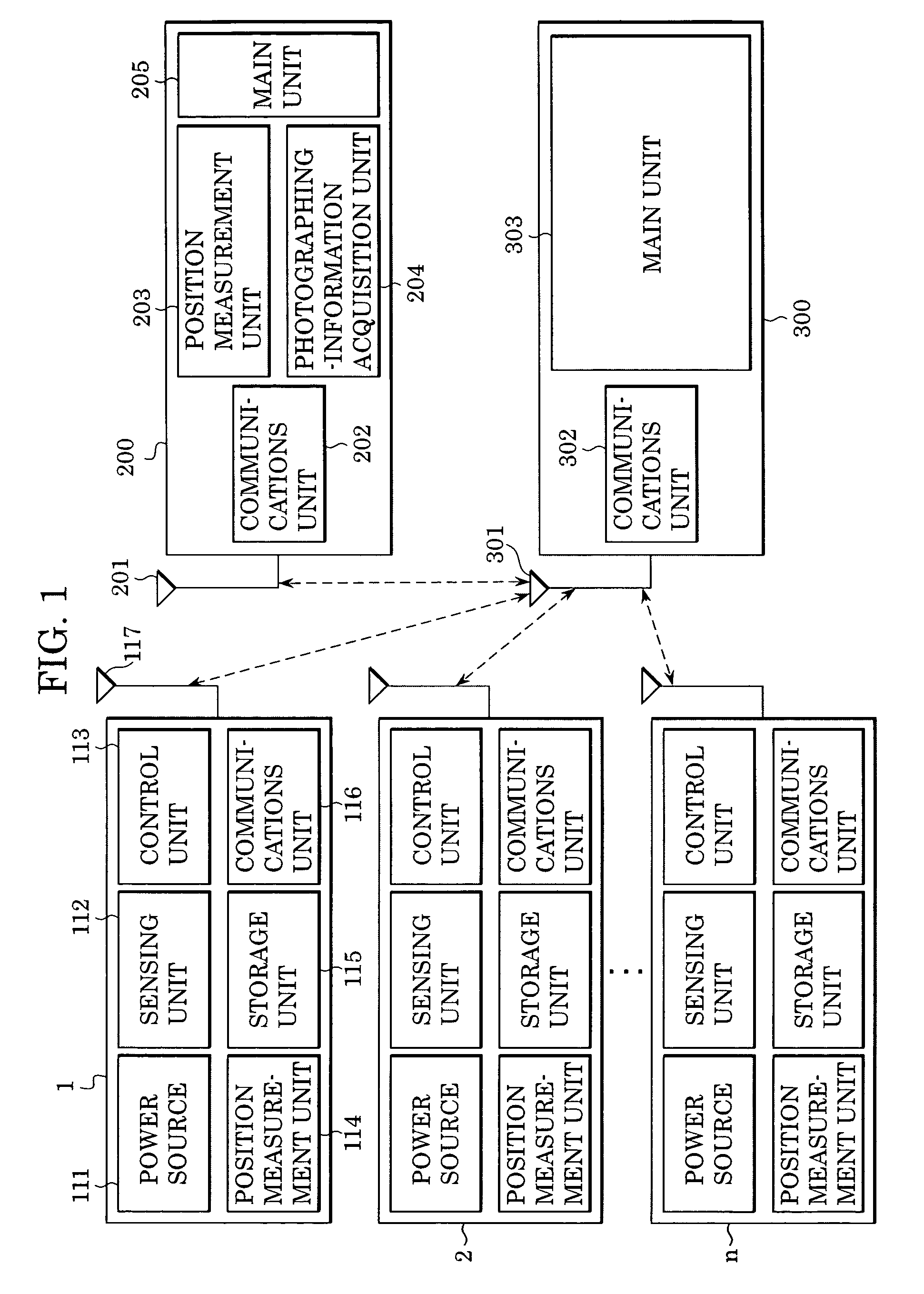
[0028]FIG. 1 is a block diagram illustrating an information collection system according to a first embodiment of the present invention. In this drawing, information-acquisition apparatuses 1 to n (n≧2) have the same configurations. Each of the information-acquisition apparatuses 1 to n has a power source 111, a sensing unit 112, a control unit 113, a position measurement unit 114, a storage unit 115, a communications unit 116, an antenna 117, and so forth.

[0029]The power source 111 can be, for example, a battery or a generator, or a combination of the battery and the generator. Where the battery is used, a disposable primary battery, a rechargeable secondary battery, or a capacitor / super capacitor can be used, for example. Where the generator is used, a solar panel using optoelectronic effects of an optoelectronic element, a wind-power generator using electromagnetic induction of a coil, a thermoelectric generator (a temperature-difference generator) using the Seebeck effect of a th...

second embodiment

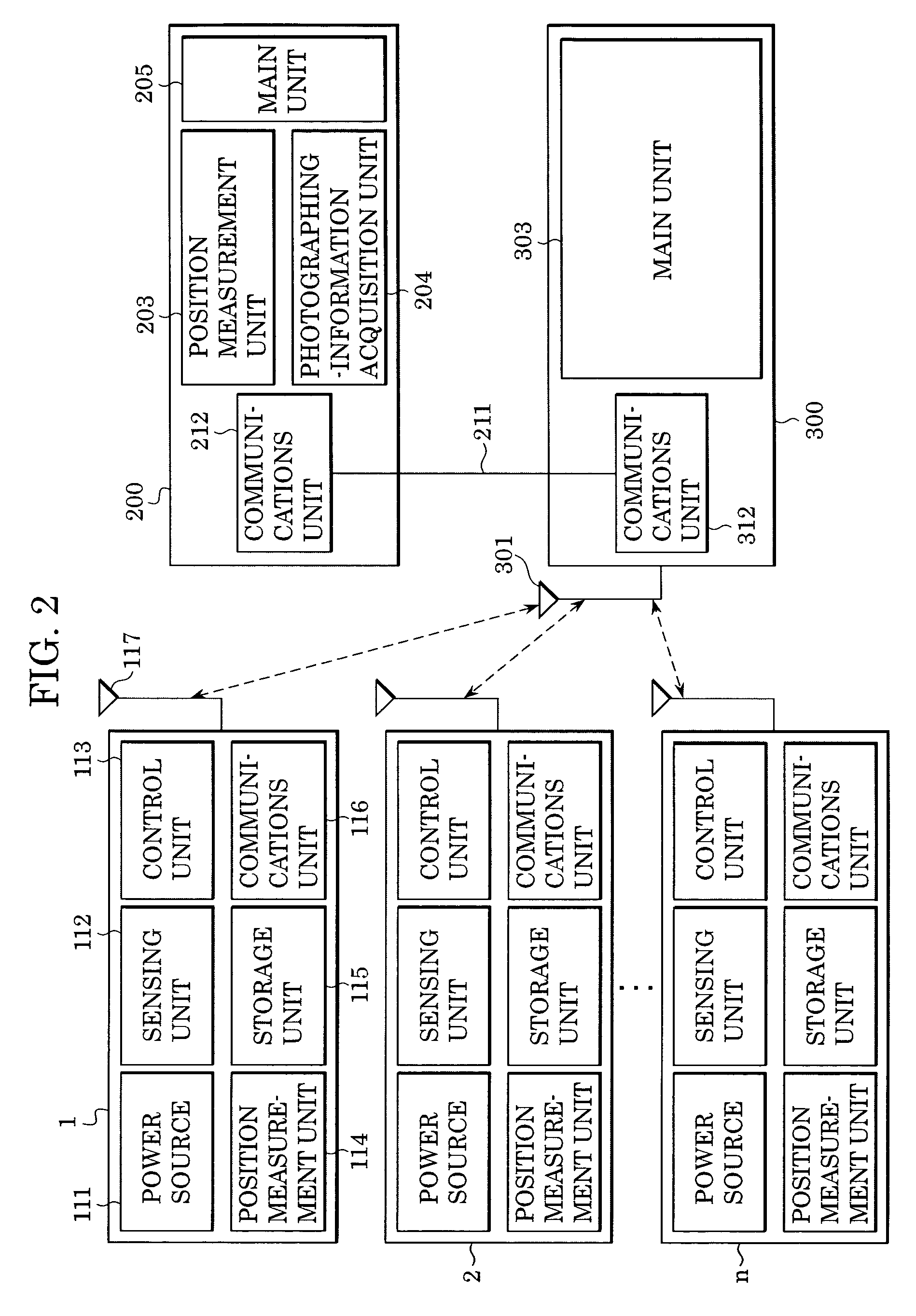
[0067]Next, an information collection system according to a second embodiment of the present invention will now be described with reference to FIG. 2. Since the configuration of the information-acquisition apparatuses 1, 2, . . . , n (where n≧2) shown in this drawing is the same as those of the first embodiment, the description thereof is omitted.

[0068]The photographing apparatus 200 of this embodiment is the same as that of the first embodiment except that a communications unit 212 is provided in place of the communications unit 202. The information collection apparatus 300 of this embodiment is the same as that of the first embodiment except that a communications unit 312 is provided in place of the communications unit 302.

[0069]The communications unit 212 is wire-connected to the communications unit 312 by a communications line 211. Otherwise, the photographing apparatus 200 may be integrated into the information collection apparatus 300 and the signal lines of the above-describe...

third embodiment

[0071]An information collection system according to a third embodiment of the present invention will now be described. FIG. 6 is a sequence chart illustrating second procedural steps performed for collecting information by the information collection apparatus 300 according to the first embodiment or the second embodiment. In this drawing, the sequence flows from left to right.

[0072]In this drawing, the information-acquisition apparatuses 1 to n are customized into microphones 1 to n for obtaining continuous speech information. The photographing apparatus 200 is customized into a video camera 200 for obtaining continuous image information.

[0073]Procedural steps performed in sequence S20 are the same as those of sequence S10 shown in FIG. 5. That is to say, sequence S20 indicates procedural steps performed by the information collection apparatus 300 for collecting the position information from each of the microphones 1 to n and the video camera 200. It is to be noted that sequence S20...


PUM


Abstract

An information collection system including an information collection apparatus, a photographing apparatus and information acquisition apparatuses. The information collection apparatus collects information on the information acquisition apparatuses and the photographing apparatus. The information collection apparatus selects at least one of the information-acquisition apparatuses based on the collected information, and collects information about a predetermined position by communicating with the selected information-acquisition apparatus.

Description

[0001]This application claims priority from Japanese Patent Application No. 2003-385164 filed Nov. 14, 2003, which is hereby incorporated by reference herein.BACKGROUND OF THE INVENTION[0002]1. Field of the Invention[0003]The present invention relates to an information collection apparatus for collecting information data transmitted from a photographing apparatus and information acquisition apparatuses.[0004]2. Description of the Related Art[0005]Recently, sensing-network systems including a network and a plurality of sensors connected thereto are receiving attention. For example, Nikkei Electronics, Jul. 15, 2002, pp. 99-129, discloses several sensing-network systems. One of the example sensing-network systems disclosed in the above-described document includes numerous sensors distributed in a forest for collecting information on the forest, such as amount of oxygen generated, amount of CO2 absorbed, temperature, humidity, and so forth. This sensing-network system can be used for e...

Claims


Application Information

Patent Timeline
Patent Type & Authority Patents(United States)
IPC IPC(8): H04N5/232G08C17/00G03B7/26H04M11/00H04N7/18H04N9/47H04Q9/00
CPCG03B7/26H04N1/00127H04N1/00323H04N2201/0055H04N2201/0084
Inventor IIZUKA, YOSHIO
Owner CANON KK
Why Eureka
Try Eureka