Control unit and method for vehicle

a control unit and vehicle technology, applied in the direction of machines/engines, instruments, transportation and packaging, etc., can solve the problems of increasing the shift shock by sudden increase in engine torque, slipping of friction elements of the transmission, and increasing the slippage of the clutch, so as to reduce the shift shock

Inactive Publication Date: 2008-11-11
TOYOTA JIDOSHA KK
View PDF9 Cites 4 Cited by
  • Summary
  • Abstract
  • Description
  • Claims
  • Application Information

AI Technical Summary

Benefits of technology

[0012]The invention provides a control unit and method for a vehicle equipped with a stepped automatic transmission, which accurately calculates the target torque required to be output from a drive power source of the vehicle while the gears are being changed, thereby reducing shift shock due to fluctuation in torque from the drive power source.
[0014]The control unit according to the first aspect of the invention calculates, as the gear-change progress, the degree to which the gear-change has proceeded in the inertia phase, and calculates the virtual gear ratio so that the virtual gear ratio corresponds to the gear-change progress. Thus, if the gear-change progress is little, a virtual gear ratio, on which the gear ratio before the gears are changed is reflected more greatly than the gear ratio after the gears are changed, is obtained. On the other hand, if the gear-change progress is large, a virtual gear ratio, on which the gear ratio after the gears are changed is reflected more greatly than the gear ratio before the gears are changed, is obtained. In this manner, the target torque is calculated based on the continuous virtual gear ratio in the inertia phase, which is calculated by interpolating a value between the gear ratio before the gears are changed and the gear ratio after the gears are changed. Accordingly, it is possible to change the target torque continuously. Thus, it is possible to absorb shock caused by fluctuation in the torque output from the drive power source of the vehicle. Especially, because continuous virtual gear ratio is used, it is possible to change the target torque continuously even when a one-way clutch is idling. As a result, in the vehicle equipped with a stepped automatic transmission, it is possible to accurately calculate the target torque required to be output from the drive power source of the vehicle while the gears are being changed, whereby shift shock caused by torque fluctuation is suppressed.

Problems solved by technology

However, if the actual gear ratio calculated based on the rotational speeds of the input shaft and the output shaft of the transmission is used, shift shock may be increased by sudden increases in the engine torque due to changes in the calculated value of the actual gear ratio.
Such changes occur due to a malfunction in a sensor or disengagement of a one-way clutch.
While the gears are being changed, friction elements of the transmission are slipping.
For example, only the torque within the capacity of a clutch, one of the friction elements, is transferred, and the remaining torque just contributes to increases in slippage of the clutch.
In such a state, if the gear ratio used to calculate the target engine torque is changed, the engine torque may suddenly changes, and, consequently, shock may be caused.
If the engine torque is controlled using the actual gear ratio while the gears are being changed, the engine torque may not be performed stably if the rotational speeds fluctuate or the detection accuracy of the sensor is not sufficiently high.
However, in the control of the torque output from the engine, which is the drive power source of the vehicle, described in Japanese Patent Application Publication No. 2001-347854 (JP-A-2001-347854), such inconveniences are not taken into account.

Method used


Image

  • Control unit and method for vehicle
  • Control unit and method for vehicle
  • Control unit and method for vehicle

Examples


Embodiment Construction

[0022]Hereinafter, an embodiment of the invention will be described in detail with reference to accompanying drawings. In the following description, the same or corresponding portions will be denoted by the same reference numerals. Names and functions thereof are also identical to each other, and therefore, redundant explanation thereof will be omitted.

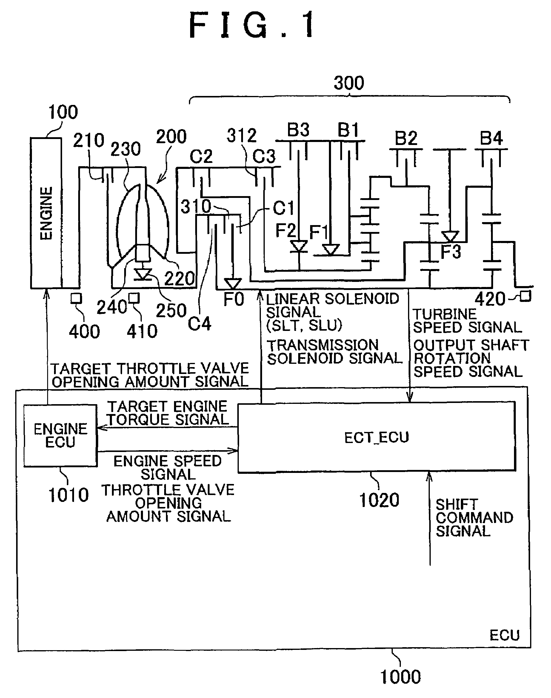
[0023]A power train of a vehicle including a control unit according to the embodiment will be described. The control unit according to the embodiment of the invention is an electronic control unit (ECU) 1000 shown in FIG. 1. In the embodiment, an automatic transmission is provided with a torque converter, and includes a planetary gear speed reduction mechanism, and the vehicle is equipped with an engine that serves as a drive power source of the vehicle.

[0024]As shown in FIG. 1, the power train of the vehicle includes an engine 100, a torque converter 200, an automatic transmission 300, and the ECU 1000. The output shaft of the engine...


PUM


Abstract

An ECT_ECU performs a program including: a step of determining whether the gears are being changed or the gears are not being changed; a step of setting the virtual gear to the current gear, if the gears are not being changed; a step of setting the virtual gear to the gear before the gears are changed, if the gears are being changed but the inertia phase has not been started; a step of setting the virtual gear to the gear after the gears are changed, if the gears are being changed and the inertia phase has been started; a step of calculating the gear-change progress α; a step of calculating the virtual gear ratio based on the virtual gear and the gear-change progress α; and a step of calculating the target engine torque using the virtual gear ratio.

Description

INCORPORATION BY REFERENCE[0001]The disclosure of Japanese Patent Application No. 2006-006017 filed on Jan. 13, 2006 including the specification, drawings and abstract is incorporated herein by reference in its entirety.BACKGROUND OF THE INVENTION[0002]1. Field of the Invention[0003]The invention relates generally to a control unit and method for a vehicle equipped with a stepped automatic transmission. More specifically, the invention relates to such control unit and method that prevents shift shock from being caused during drive power demand control.[0004]2. Description of the Related Art[0005]A control technique called “drive power control” is often employed in a vehicle equipped with an automatic transmission and an engine which is controllable to output a required torque independently of an accelerator pedal operation performed by a driver. According to the drive power control, a positive or negative target drive power is calculated based on the amount by which the accelerator ...

Claims


Application Information

Patent Timeline
Patent Type & Authority Patents(United States)
IPC IPC(8): G06F7/00B60W10/04B60W10/06B60W10/10B60W10/11B60W10/115B60W30/19B60W30/20F02D29/00F16H59/42F16H59/68F16H59/70F16H61/04F16H61/68F16H61/684F16H61/686F16H63/40F16H63/50
CPCF16H63/502F16H61/0437F16H61/686Y10T477/688F16H2200/201F16H2306/42F16H2200/0052
Inventor KUWAHARA, SEIJIKAIGAWA, MASATO
Owner TOYOTA JIDOSHA KK
Why Eureka
Try Eureka