
Torque modulation in a hybrid vehicle downshift during regenerative braking

a hybrid vehicle and powertrain technology, applied in the field of hybrid vehicle powertrains, can solve the problems of significant negative torque at the input of the transmission, shift shock, and waste of energy, and achieve the effect of reducing shift shock

Active Publication Date: 2016-11-15
FORD GLOBAL TECH LLC
View PDF33 Cites 5 Cited by
  • Summary
  • Abstract
  • Description
  • Claims
  • Application Information

AI Technical Summary

Benefits of technology

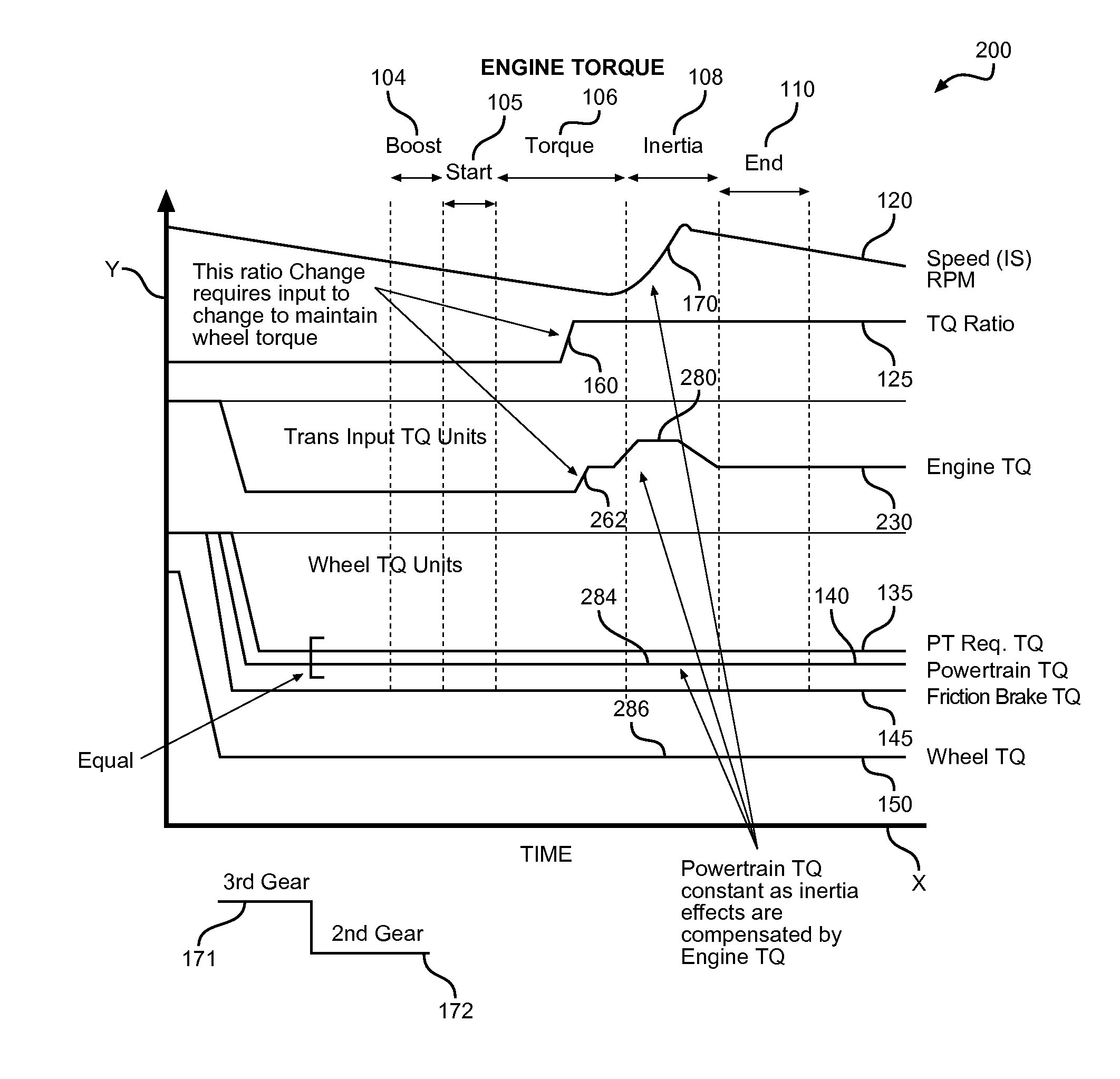
[0009]The present invention is directed to a controller and a control strategy for reducing shift shock in a hybrid electric vehicle powertrain during a downshift conducted while the vehicle is in a regenerative braking mode by maintaining total powertrain torque constant at a desired target during the downshift. The hybrid electric vehicle has an engine, an electric motor, a battery connected to the electric motor, a set of drive wheels, an automatic transmission including multiple gear ratios for receiving a first input torque generated by the engine and delivering a total powertrain output torque to the set of drive wheels, and a controller configured to effect a downshift between gear ratios during regenerative braking while maintaining the output torque at a constant value.
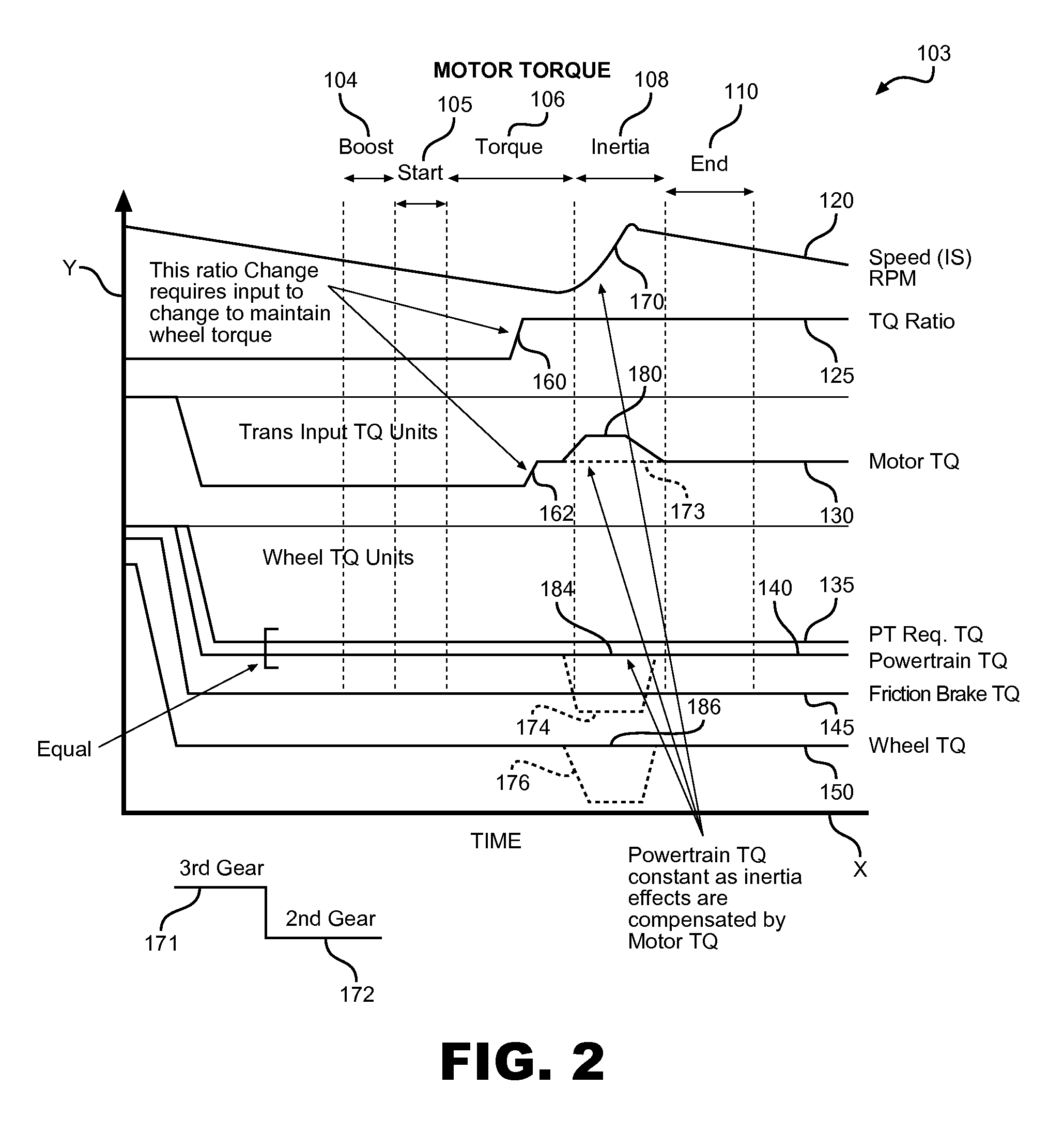
[0010]Although shifting during regenerative braking tends to cause variations in the total powertrain output torque that is felt as a shift shock, the controller reduces the shift shock by sending control signals to the powertrain to control the amount of total powertrain output torque delivered from the transmission to the set of drive wheels. Specifically, the controller regulates a downshift between gear ratios during regenerative braking while maintaining the output torque constant during the downshift. The controller also provides control signals to the engine and motor for generating a first input torque with the engine and generating a second input torque with the motor. The controller preferably takes further measures to reduce shift shock, such as maintaining the total powertrain output torque at a constant level by modulating the first input torque or second input torque and varying a friction braking force applied to drive wheels of the vehicle through friction brakes to counteract variations which tend to be caused by the regenerative braking in the transmission during the downshift. The controller has three preferable modes including: modulating just engine torque; modulating just electric motor torque; or simultaneously modulating both electric motor and engine torque. Preferably, the controller removes the regenerative braking before the downshift and reinstates the regenerative braking after the downshift. In another embodiment, the controller regulates the amount of regenerative braking during both torque and inertia phases of the downshift. In particular, the controller also decreases an amount of friction braking during a torque phase of the downshift and restores the amount of friction braking during the inertia phase. The controller determines timing for applying friction braking by predicting a lag time associated with the friction braking and compensating for the lag time.

Problems solved by technology

In some hybrid electric vehicles, since the motor is located between the engine and the transmission, the coast downshift is done with a significant level of negative torque at the input to the transmission.
The negative torque in the hybrid powertrain will cause shift shock in a manner similar to that found in a power-on upshift in a conventional powertrain.
Torque modulation using spark retardation will satisfy the timing and repeatability requirements to satisfy shift quality targets, but this wastes some energy during the shift, which can only reduce torque, not increase it.
Torque modulation also can be accomplished by using a fuel cut-off to reduce engine torque, but restoring engine torque following a shift event often is not repeatable using fuel control.
In the case of downshifts during regenerative braking, drivability problems result if shift shock is not addressed.
However, such methods have the problem that the transfer to friction braking leads or lags the duration of the shift event and such solutions tend to require overly complicated control systems.

Method used


Image

  • Torque modulation in a hybrid vehicle downshift during regenerative braking
  • Torque modulation in a hybrid vehicle downshift during regenerative braking
  • Torque modulation in a hybrid vehicle downshift during regenerative braking

Examples


Embodiment Construction

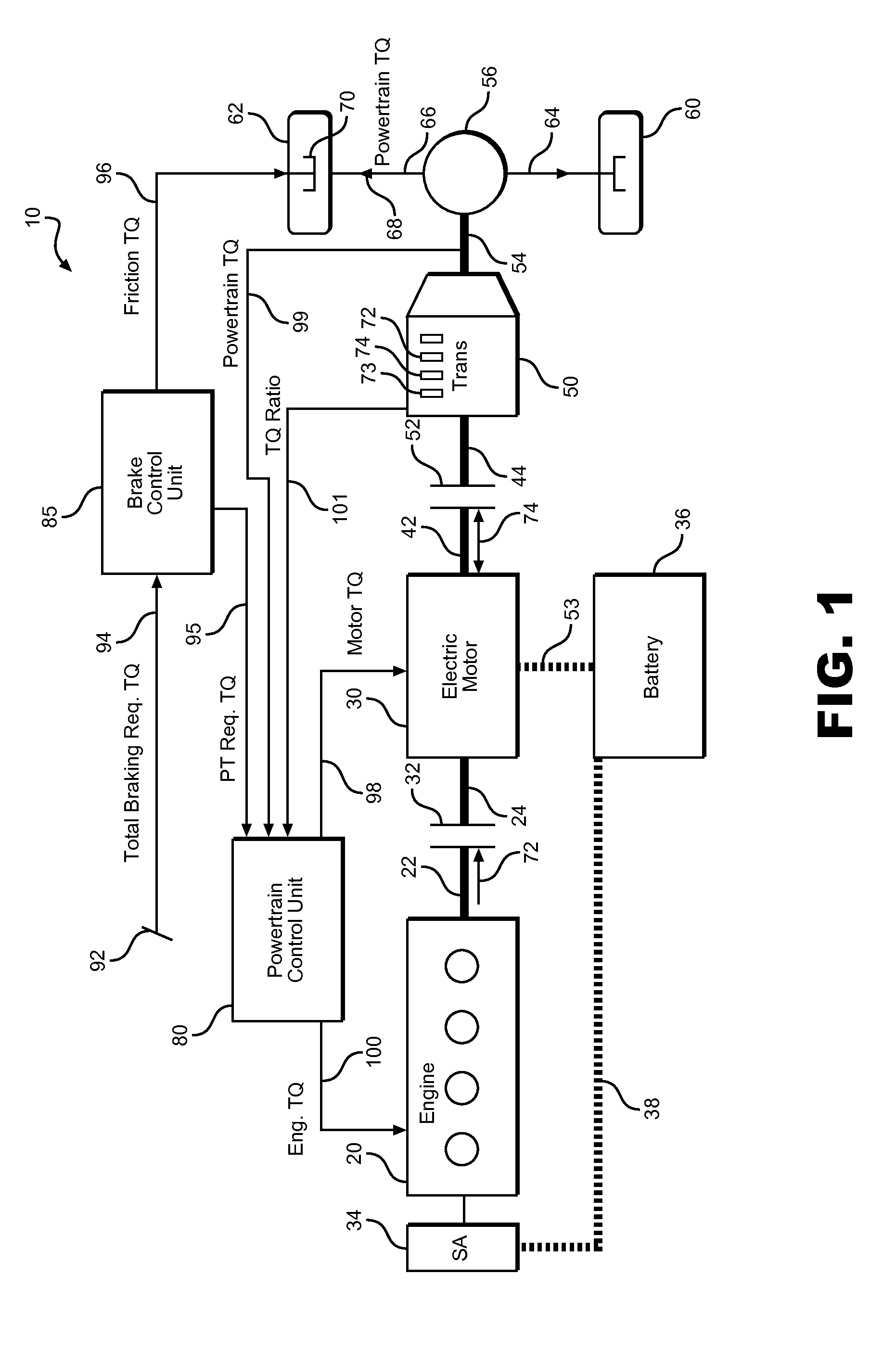
[0017]With initial reference to FIG. 1, there is schematically shown a hybrid electric vehicle powertrain system 10 for a hybrid electric vehicle. As depicted, an internal combustion engine 20 has an output shaft 22 connected to an input shaft 24 of an electric motor 30 through an engine clutch 32. Internal combustion engine 20 is also connected to a starter motor 34 used to start engine 20. Starter motor 34 is also connected to a battery 36 through wiring 38 so as to be also used as a generator to produce electric energy that is stored in a battery 36. Electric motor 30 has an output shaft 42 that is connected to an input shaft 44 of an automatic transmission 50 through a motor clutch 52. Electric motor 30 is also linked to battery 36 through a connecting wiring 53. Transmission 50 includes multiple gear ratios and is connected to a drive shaft 54 that, in-turn, is connected to a differential 56. Left and right drive wheels 60, 62 are connected to differential 56 through left and r...


PUM


Abstract

A controller and a control strategy minimizes shift shock in a hybrid electric vehicle during a downshift conducted while the vehicle is in a regenerative braking mode by maintaining total powertrain torque at a desired target during the downshift. The controller has three preferable modes including modulating just engine torque, modulating just electric motor torque or simultaneously modulating both motor and engine torque.

Description

BACKGROUND OF THE INVENTION[0001]1. Field of the Invention[0002]The present invention pertains to the art of hybrid vehicle powertrains and, more specifically, modulating torque in a hybrid vehicle powertrain during a ratio change of the transmission that occurs during regenerative braking.[0003]2. Discussion of the Prior Art[0004]A hybrid vehicle powertrain typically includes an electric motor, such as a high voltage induction motor, wherein driving torque of an engine is supplemented with electric motor torque produced by the electric motor. The combined engine torque and electric motor torque is transferred to vehicle traction wheels through a multiple ratio power transmission mechanism. A wet clutch assembly may be included in the power flow path between a torque input element of the multiple-ratio power transmission mechanism and a crankshaft of the engine. An example of a hybrid electric vehicle powertrain of this type is disclosed in U.S. Pat. No. 6,585,066, which is assigned...

Claims


Application Information

Patent Timeline
Patent Type & Authority Patents(United States)
IPC IPC(8): B60W20/00F16H63/50F16H61/04B60W10/188B60W30/18B60W30/19B60W10/11B60K6/48B60W30/20B60W10/10F16H59/00B60W10/18B60W10/08B60W10/06
CPCB60W10/06B60K6/48B60W10/08B60W10/10B60W10/11B60W10/188B60W20/15B60W30/18127B60W30/19B60W30/20F16H61/04F16H63/502B60K2006/4825B60W2030/18081B60W2030/206B60W2710/0666B60W2710/083B60W2720/30B60Y2200/92B60Y2300/18125Y02T10/6221Y02T10/6252Y02T10/6286Y10S903/93Y02T10/62B60W2720/106B60W20/30B60W10/115B60W10/184B60W20/10B60Y2300/19B60Y2400/112B60Y2400/73
Inventor NEFCY, BARNEY DCONNOLLY, FRANCIS THOMASCOLVIN, DANORTMANN, WALT JOSEPHKRASKA, MARVIN PAULCROMBEZ, DALE SCOTTYAMAZAKI, MARK STEVEN
Owner FORD GLOBAL TECH LLC
Learn More