Portable apparatus for separating sample and detecting target analytes

Inactive Publication Date: 2008-11-18
SANDIA NAT LAB
View PDF20 Cites 26 Cited by
  • Summary
  • Abstract
  • Description
  • Claims
  • Application Information

AI Technical Summary

Benefits of technology

[0011]According to another aspect of the present invention, a portable device of analyzing a liquid sample is provided. The device includes a housing including a top plate, a bottom plate, and a back plate. The housing encloses means for receiving the liquid sample and an analysis module including a module for separating the sample into its compon

Problems solved by technology

However, the performance offered by present microfluidic devices is limited by the interfaces between the microfluidic device and the macroscopic world.
Connecting detection units including light sources and other detectors, power sources necessary for any actuators or detectors, and macroscopic amounts of reagent fluid and/or sample fluid to present microfluidic devices is cumbersome—often requiring a lengthy p

Method used


Image

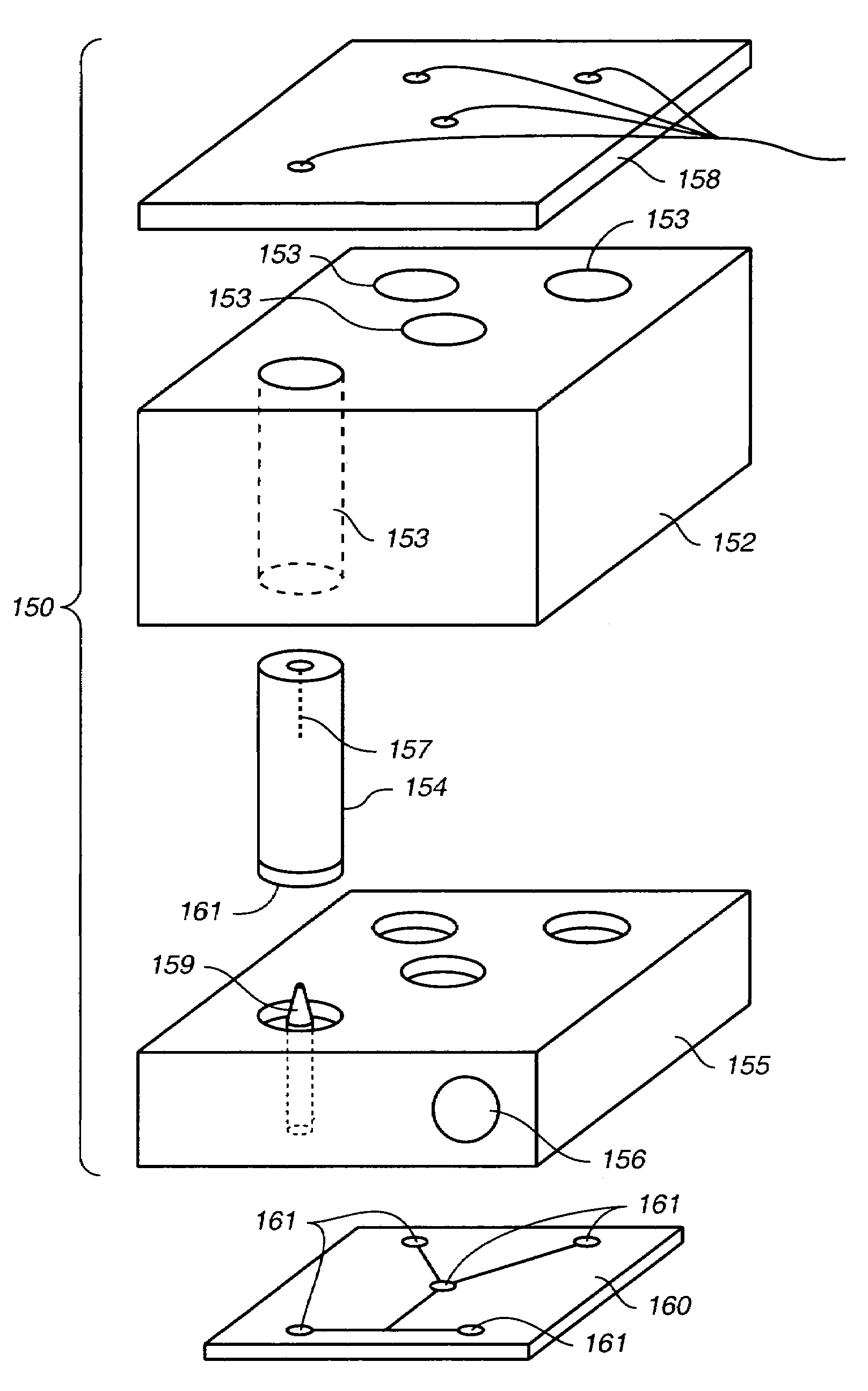
  • Portable apparatus for separating sample and detecting target analytes
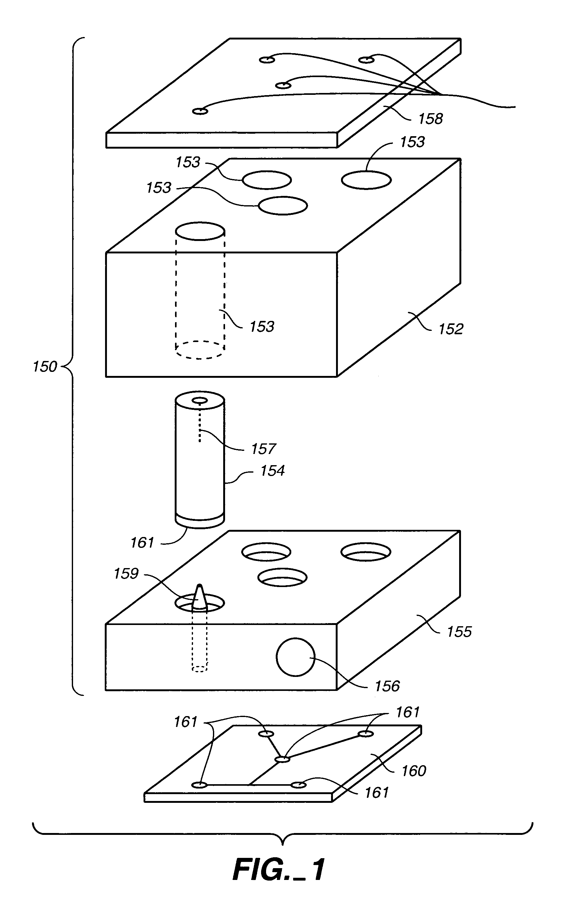
  • Portable apparatus for separating sample and detecting target analytes
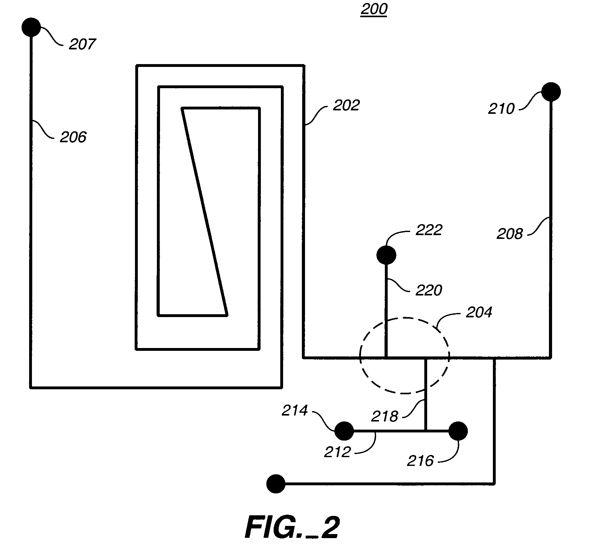
  • Portable apparatus for separating sample and detecting target analytes

Examples


example 1

Microfluidic Chip Fabrication

[0116]The microchip was fabricated from Corning 7980 fused silica wafers (100 mm diameter, 0.75 mm thickness using standard photolithography, wet etch, and bonding techniques. Fused Silica wafers were PECVD deposited with amorphous silicon (150 nm), which served as the hard mask. A 7.5-micron thick layer of positive photoresist was spin-coated and soft-baked (90 C, 5 minutes). The mask pattern was transferred to the photoresist by exposing it to UV light in a contact mask aligner. After exposure, the photoresist was developed and hard-baked (125 C, 30 minutes). Exposed silicon was etched in a plasma etch tool. Silicon etch process consisted of a 30 second oxygen ash @ 200 W DC & 25 mTorr, followed by 150 second SF6 @ 200 W DC & 50 mTorr. The subsequently exposed glass was etched with a 49% HF solution. Via access holes were drilled in the cover plate (Corning 7980) with diamond-tipped drill bits. The etched wafers and drilled cover plates were cleaned wi...

example 2

A portable, modular analysis device

[0117]FIG. 4 shows an exploded view of an embodiment of the device, indicated generally at 10. Externally, the device is comprised of a top (or cover) plate 11, a case or shell 12, and a back cover 13—together, a housing. In the embodiment illustrated here, top plate 11 incorporates a 4-button menu-driven interface 14 and lighted LCD screen 15 for programming separation conditions and for presenting analytical results, a serial port computer connection 16 and 6-volt electrical connection 18 for use when wall power is available.

[0118]FIG. 5 is a view of the underside of cover plate 11 showing the general arrangement of an embodiment of a power module on a high voltage board carrier 21. The power module comprises a plurality of high voltage boards 22 that provide the electric field required to drive the chemical separations and manipulate fluid samples for such operations as sample loading in each microchannel. In this embodiment, the high voltage bo...


PUM

PropertyMeasurementUnit
Flow rateaaaaaaaaaa
Lengthaaaaaaaaaa
Currentaaaaaaaaaa

Abstract

Portable devices and methods for determining the presence of a target analyte using a portable device are provided. The portable device is preferably hand-held. A sample is injected to the portable device. A microfluidic separation is performed within the portable device and at least one separated component detected by a detection module within the portable device, in embodiments of the invention. A target analyte is identified, based on the separated component, and the presence of the target analyte is indicated on an output interface of the portable device, in accordance with embodiments of the invention.

Description

CROSS-REFERENCE TO RELATED APPLIATIONS[0001]This application claims the benefit of the filing date of U.S. Provisional Application 60 / 400,884, filed 2 Aug. 2002, entitled “A Modular Device for Microscale Biotoxin Detection”, hereby incorporated by reference in its entirety.STATEMENT REGARDING FEDERALLY-FUNDED RESEARCH[0002]This invention was made with government support under contract No. DE-AC04-94AL85000 awarded by the U.S. Department of Energy to Sandia Corporation.FIELD OF THE INVENTION[0003]The invention relates to the detection of target analytes in a sample fluid, particularly to a modular device used to detect target analytes in a sample fluid.BACKGROUND OF THE INVENTION[0004]Devices for manipulating fluids on the microscale have been developed to store, hold, and manipulate small amounts of fluids and have been applied to the detection of analytes in sample fluids. For example, capillary electrophoresis, generally involving the separation of charged species in solution, can...

Claims


Application Information

Patent Timeline
IPC IPC(8): G01N21/64B01D59/42G01N21/76B01L3/00B01L9/00
CPCB01L3/502715B01L9/527G01N21/645B01L3/5027B01L2200/025B01L2200/027B01L2200/10B01L2300/0672B01L2300/0816G01N2021/6482
Inventor RENZI, RONALD F.WALLY, KARLCROCKER, ROBERT W.STAMPS, JAMES F.GRIFFITHS, STEWART K.FRUETEL, JULIA A.HORN, BRENT A.SHOKAIR, ISAAC R.YEE, DANIEL D.VANDERNOOT, VICTORIA A.WIEDENMAN, BOYD J.WEST, JASON A. A.FERKO, SCOTT M.
Owner SANDIA NAT LAB
Why Eureka
Try Eureka