Electronic controller matching engine power to alternator power and maintaining engine frequency for a free-piston stirling engine driving a linear alternator

a linear alternator and electric controller technology, applied in the direction of motor/generator/converter stopper, dynamo-electric converter control, instruments, etc., can solve the problems of engine stall, damage to internal collisions, and bulky and expensive tuning capacitors

Inactive Publication Date: 2008-11-18
SUNPOWER
View PDF8 Cites 22 Cited by
  • Summary
  • Abstract
  • Description
  • Claims
  • Application Information

AI Technical Summary

Problems solved by technology

However, such tuning capacitors are bulky and expensive so it is desirable to eliminate the tuning capacitor.
If the power transferred to the alternator exceeds the power generated by the FPSE, the engine will stall.
If the power transferred to the alternator is less than the power generated by the FPSE, the piston stroke will increase uncontrollably and can cause damaging internal collisions and engine temperature will slowly increase over time.
However, that is an insufficient control for at least two reasons.
First, the rate of temperature change that can be accomplished is relatively slow, far too slow to respond in time to prevent either engine stalling or piston over-stroking.
Therefore, modulating thermal input power and temperature not only is too slow but also reduces engine efficiency because it does not maintain the highest possible input head temperature.
Although embodiments of the invention advantageously include a fuel combustion control system that maintains a constant temperature that is as hot as the engine materials can withstand, that alone is not a viable option for controlling engine power output and piston stroke and maintaining the power balance described above.
However, this is obviously undesirable because it simply dissipates excess power produced by the engine in order to maintain the power balance and consequently reduces efficiency by wasting heat energy and therefore wasting fuel.
Consequently, it is a problem to design a control system that accomplishes both (1) matching the power delivered to the alternator by the FPSE to the power demanded by the electrical load plus electrical losses; and (2) maintaining a constant output voltage.
The problem is that, if the electrical power demand of the electrical load decreases and the stroke is decreased to reduce FPSE power, the induced voltage drops.

Method used


Image

  • Electronic controller matching engine power to alternator power and maintaining engine frequency for a free-piston stirling engine driving a linear alternator
  • Electronic controller matching engine power to alternator power and maintaining engine frequency for a free-piston stirling engine driving a linear alternator
  • Electronic controller matching engine power to alternator power and maintaining engine frequency for a free-piston stirling engine driving a linear alternator

Examples


Embodiment Construction

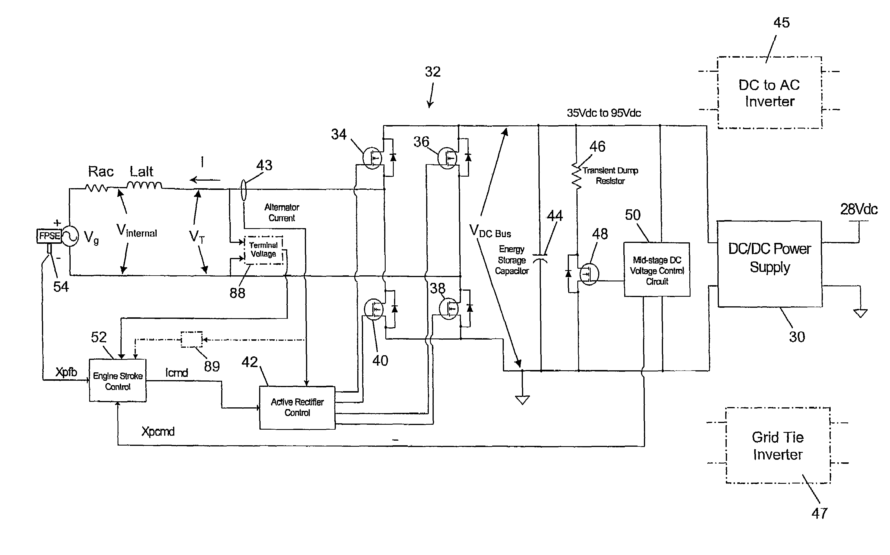
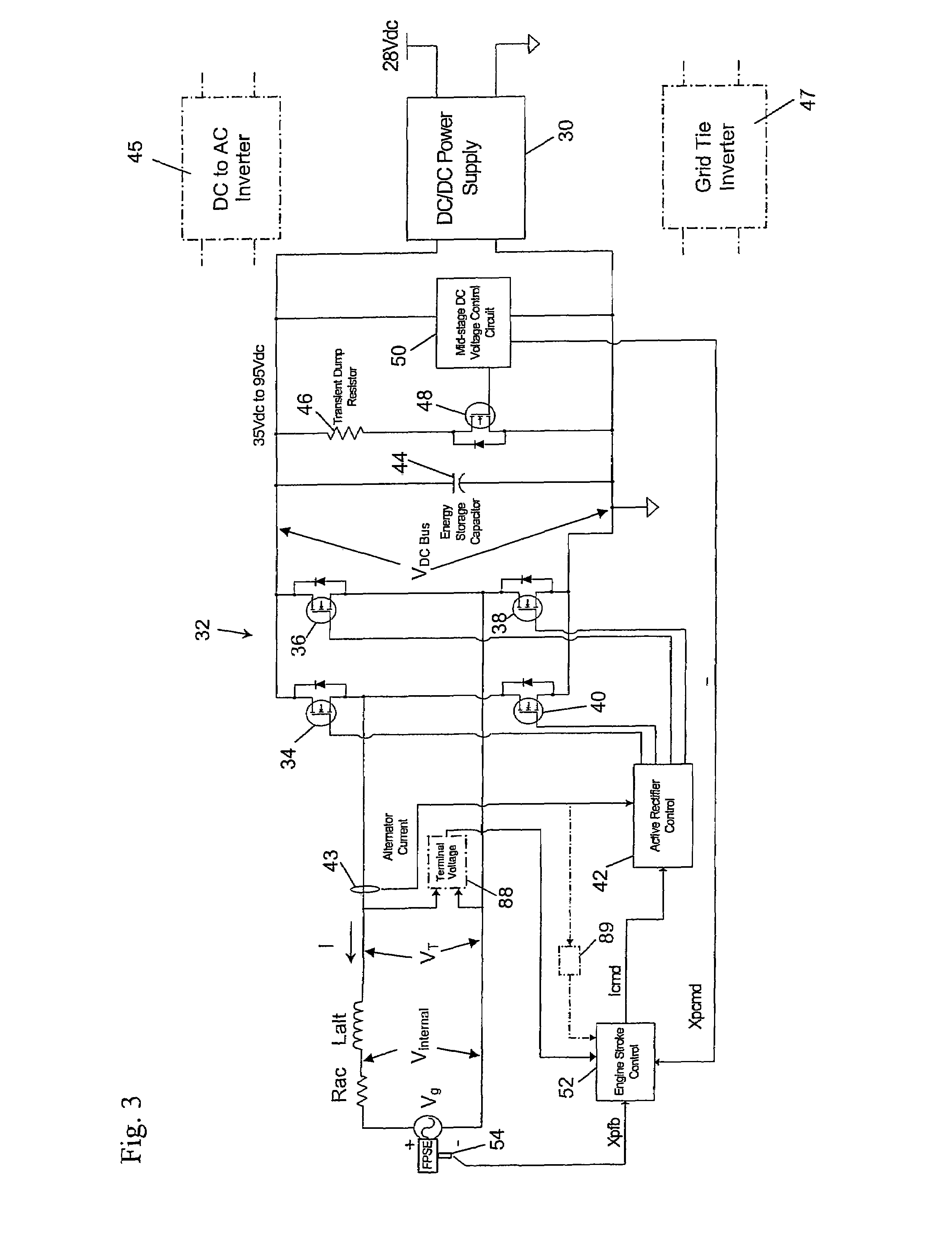
[0026]The apparatus of the invention is an improved, free-piston Stirling engine driving a linear alternator having its output current controlled by a switching mode rectifier where the improvement comprises a combination of particular negative feedback control loops controlling the switching mode rectifier. The concepts of the invention are best illustrated by means of a feedback control loop diagram of the type that those skilled in the feedback control art are familiar with. However, the feedback control loop diagram can be better understood if preceded by an explanation of an embodiment of the physical circuitry that is represented by the feedback control loop diagram. This description of the invention includes several variables and parameters and they are collected together and defined at the end of this description.

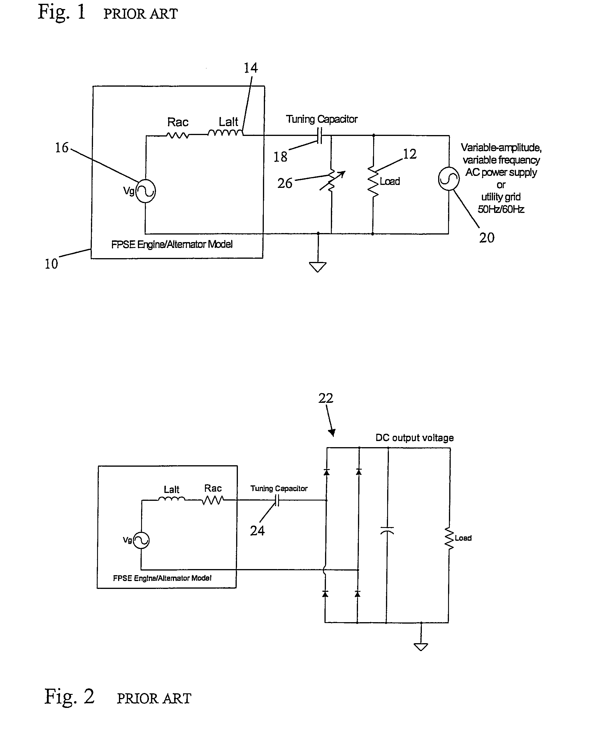
[0027]FIG. 3 is a schematic diagram of an embodiment of the invention. The alternator that is driven by the free-piston Stirling engine is, as in FIGS. 1 and 2, sho...


PUM


Abstract

A feedback control method and circuit for inclusion in a control system of an electrical power generating source that comprises a free piston Stirling engine driving a linear alternator. An instantaneous value of a variable, Vinternal, is continuously derived from other sensed and computed parameters and used in a negative feedback control loop of the control system to control engine piston stroke in order to maintain the power produced by the engine equal to the power transferred from the engine to the alternator. Vinternal is the sum of the voltage induced on the alternator winding and the voltage across the equivalent circuit lumped resistance of the alternator winding and a switching mode rectifier connects the alternator winding to an energy storage capacitor or battery. A negative feedback, alternator current control loop has an output connected to the pulse width modulator of the switching mode rectifier and has a feedback circuit comprising a current sensor for sensing instantaneous alternator current. A negative feedback, Vinternal control loop has a feedback circuit including a piston position or velocity sensor connected to a computing circuit that the current sensor is also connected to. The computing circuit computes a signal representing Vinternal for use as the feedback signal of the Vinternal control loop. The output of the Vinternal control loop is connected as the command input to the current feedback control loop.

Description

BACKGROUND OF THE INVENTION[0001]1. Field of the Invention[0002]This invention relates generally to a free-piston Stirling engine driving a linear alternator to generate electrical power and more particularly relates to a closed loop, negative feedback control system that includes improved control loops for maintaining the mechanical power generated by the engine equal to the power transferred from the engine to the linear alternator.[0003]2. Description of the Related Art[0004]A free-piston Stirling engine (FPSE) driving a linear alternator is an attractive electrical power source because such sources are efficient, compact and light weight and can generate electrical power from heat energy supplied by a variety of fuels. A free-piston Stirling engine is a closed-cycle, reversible heat engine which converts heat into work by moving a confined volume of working gas between a relatively warmer heat acceptor and a relatively cooler heat rejector. The resulting alternating, cyclical, e...

Claims


Application Information

Patent Timeline
Patent Type & Authority Patents(United States)
IPC IPC(8): H02P11/00
CPCF02D29/06F02G1/0435F02G1/045H02P25/027F02M35/112H02P9/04F02G2280/10H02P25/032H02P27/04F01B29/10F02G1/043
Inventor KEITER, DOUGLAS E.HOLLIDAY, EZEKIEL S.
Owner SUNPOWER
Why Eureka
Try Eureka