Multi-path common mode feedback for high speed multi-stage amplifiers

a multi-stage amplifier and common-mode feedback technology, applied in the field of electronic semiconductor devices and manufacturing, can solve the problems of ineffective cmfb loop, high-speed circuit implementation problems, and need for a common-mode feedback (cmfb) circuit, and achieve the effect of low transconductance gain and large transconductan

Active Publication Date: 2008-11-18
TEXAS INSTR INC
View PDF4 Cites 17 Cited by
  • Summary
  • Abstract
  • Description
  • Claims
  • Application Information

AI Technical Summary

Benefits of technology

[0015]The invention has advantages including but not limited to one or more of the following: providing large transconductance gain at low frequencies in a CMFB loop; providing low transconductance gain at high frequencies in a CMFB loop; stabilizing the common-mode feedback (CMFB) loop in high speed fully differential two-stage amplifiers; avoiding the occurrence of latching in amplifier systems. These and other features, advantages, and benefits of the present invention can be understood by one of ordinary skill in the arts upon careful consideration of the detailed description of representative embodiments of the invention in connection with the accompanying drawings.

Problems solved by technology

One significant disadvantage of these circuits is the need for a common mode feedback (CMFB) circuit to control the CM output voltage.
In some instances, however, the CMFB loop is ineffective due to large positive feedback produced by the external network overwhelming the negative feedback loop, leading to the output staying at the rails, a condition known as “latching”.
Conventional solutions require a large bandwidth CMFB loop in order to avoid latching states, causing practical problems in implementing high-speed circuits.
The primary problem occurs during startup or during large common mode transients, in which cases the input differential pair turns off.
This may result in the output swinging to the rails and latching there.
Many operational amplifier systems have no built-in provision to avoid these latching states.
When addressing these and other problems with techniques known in the arts, it is generally more difficult to compensate the CMFB loop compared to the differential loop because of two additional poles in the former.
Since the feedback factor (β) does not affect the common mode loop bandwidth, for a design with small feedback factor, it is possible for the common mode loop bandwidth to exceed the differential loop bandwidth, A1gm3 / CC>βgm1 / CC, leading to problems with common mode instability.
This approach, however, leads to increased DC common mode error, as expressed in Equation 1.
Additionally, if I3 is less than I1, latching remains a problem.
In two stage amplifier systems these and other problems beset efforts to control larger current in common mode loops and to avoid latching.

Method used


Image

  • Multi-path common mode feedback for high speed multi-stage amplifiers
  • Multi-path common mode feedback for high speed multi-stage amplifiers
  • Multi-path common mode feedback for high speed multi-stage amplifiers

Examples


Embodiment Construction

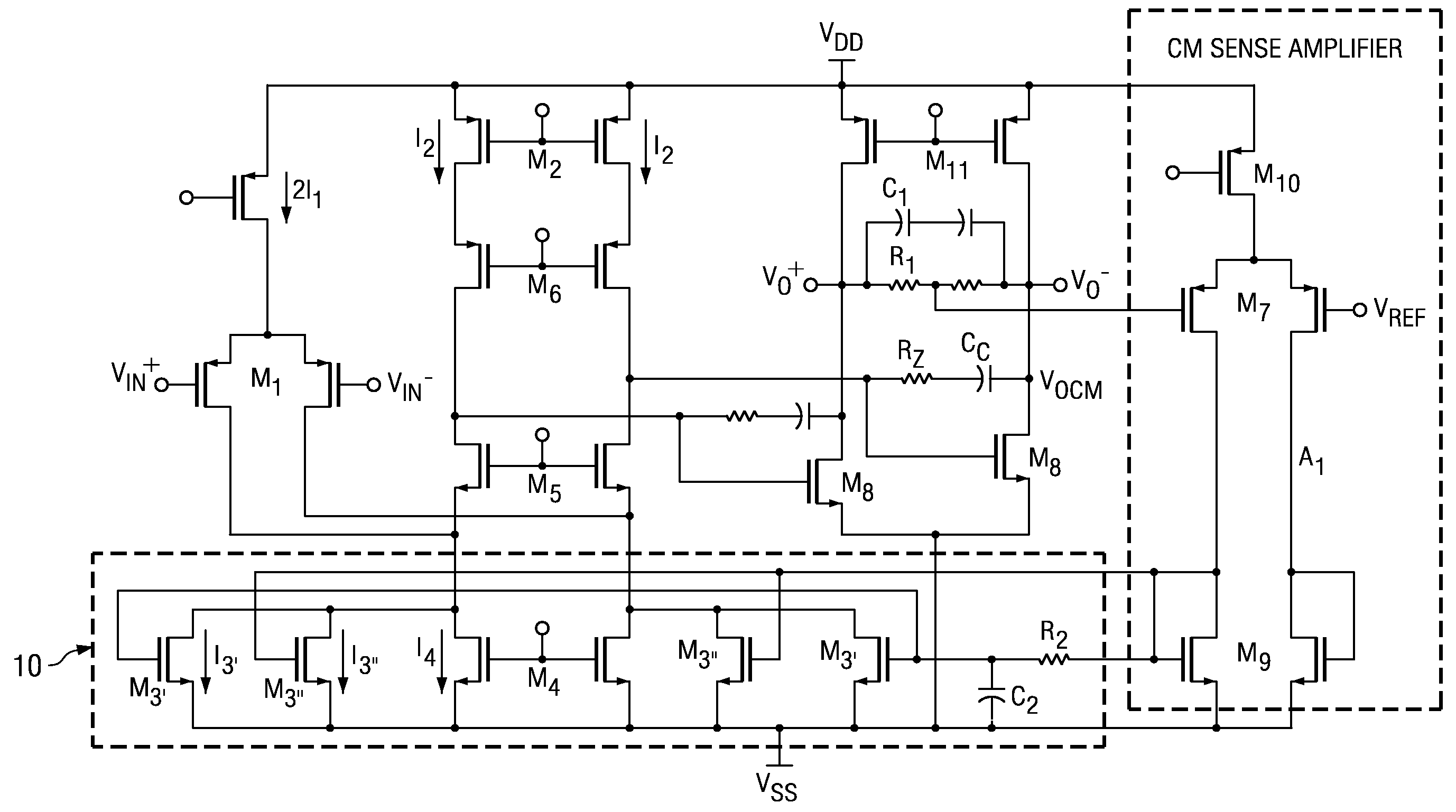
[0021]In general, the invention provides multi-path common mode feedback (CMFB) methods and systems having large transconductance gain at low frequencies, and also having a low transconductance gain at high frequencies in the CMFB loop. The multi-path techniques of the invention avoid the occurrence of latching states and maintain increased stability in the CMFB loop.

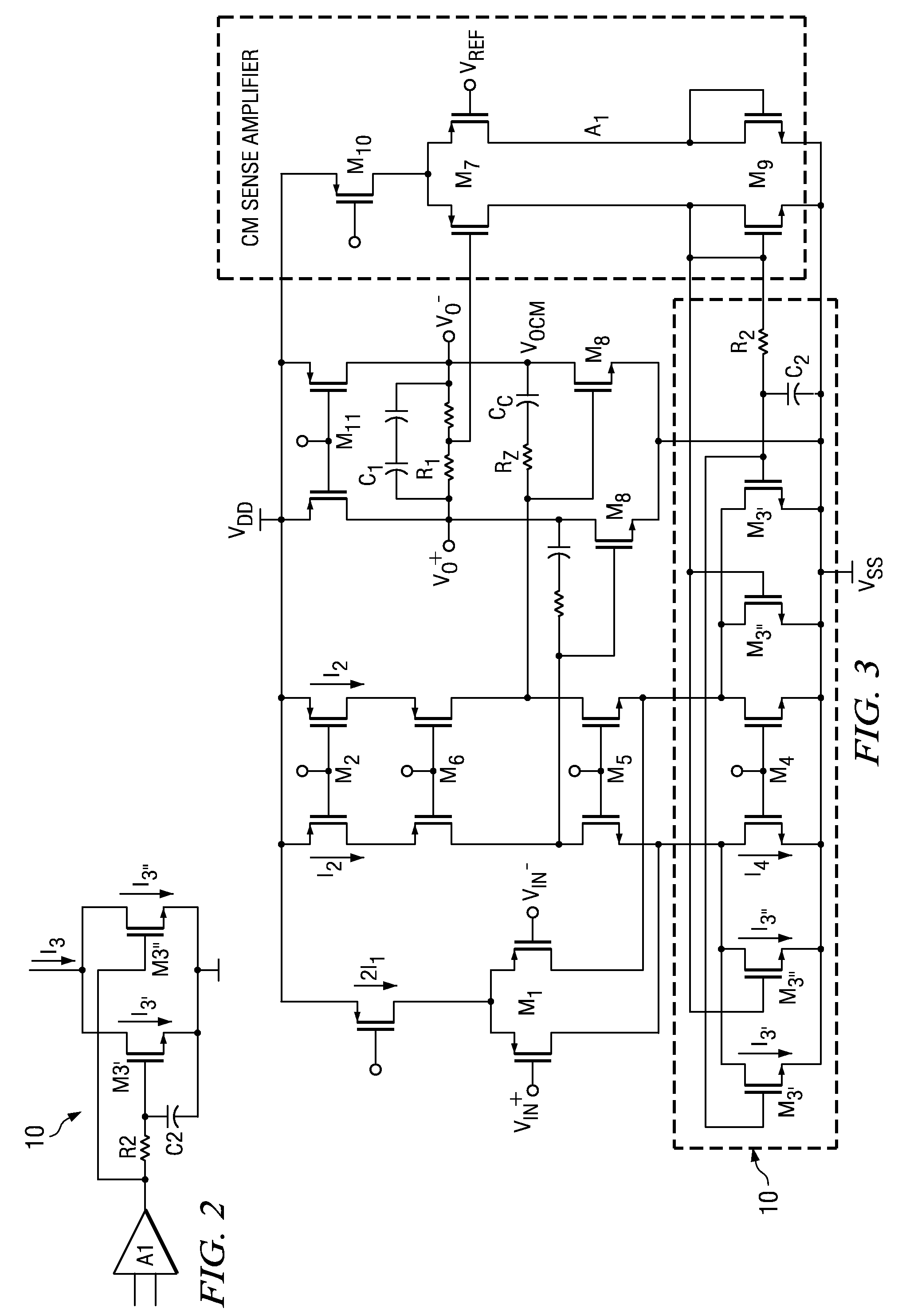
[0022]Referring to FIG. 2, a circuit method and system having a multi-path common mode loop according to the principles of the invention is shown in a simplified block diagram. Those skilled in the arts will appreciate that there are two contradictory aspects desirable for implementation of common mode feedback systems for high-speed two-stage amplifiers: for stability, it is desirable to have small bandwidth; for avoiding latching states, it is desirable to have large bias currents. As circuit illustrated in FIG. 2, the invention provides two distinct paths in the common mode feedback loop 10, herein denominated the “s...


PUM


Abstract

The invention includes methods and systems for providing a multi-path common mode feedback loop in an amplifier system. Embodiments include techniques for dividing a common mode feedback current path to provide a slow common mode feedback current path and a fast common mode feedback current path. The slow and fast paths are configured for controlling common mode feedback current within a small bandwidth.

Description

PRIORITY ENTITLEMENT[0001]This application claims priority based on Provisional Patent Application Ser. No. 60 / 772,617 filed on Feb. 13, 2006. This application and the aforementioned Provisional Patent Application have one or more common inventors and are assigned to the same entity.TECHNICAL FIELD[0002]The invention relates to electronic semiconductor devices and manufacturing. More particularly, the invention relates to systems and methods for common mode feedback loops for use with amplifier systems having an even number of gain stages.BACKGROUND OF THE INVENTION[0003]Fully differential amplifiers are widely used in modern integrated circuits in view of their relatively large output swings and relatively low susceptibility to common mode (CM) noise. One significant disadvantage of these circuits is the need for a common mode feedback (CMFB) circuit to control the CM output voltage. The main purpose of the CMFB circuit is to sense the output CM voltage and use negative feedback to...

Claims


Application Information

Patent Timeline
Patent Type & Authority Patents(United States)
IPC IPC(8): H03F3/45
CPCH03F3/45192H03F3/45654H03F3/45659H03F2203/45126H03F2203/45268H03F2203/45311H03F2203/45354H03F2203/45418H03F2203/45424H03F2203/45681H03F2203/45692
Inventor GUPTA, AMIT KUMARDHANASEKARAN, VIJAYAKUMARSOUNDARAPANDIAN, KARTHIKEYAN
Owner TEXAS INSTR INC
Why Eureka
Try Eureka