Collector ring for a center pivot irrigation machine

Active Publication Date: 2008-12-09
CONDUCTIX +1
View PDF13 Cites 20 Cited by
  • Summary
  • Abstract
  • Description
  • Claims
  • Application Information

AI Technical Summary

Benefits of technology

[0013]It is therefore a principal object of the invention to provide a collector ring for a center pivot irrigation machine which permits the mounting of a stationary communication device above the span structure without requiring the communication device wires to electrically pass through the collector rings of the collector ring assembly.

Problems solved by technology

Due to increasing fuel and labor costs, the demand for remote control of mechanized irrigation systems such as center pivot irrigation systems is increasing.
One of the limitations associated with the remote control of mechanized irrigation systems is the height at which the antenna or communication device can be mounted at the center pivot structure.
Because center pivot irrigation systems move in a full-circle rotation, communication devices such as antennas are typically mounted below the full-circle rotating span structure, which limits the mounting height of the antenna or communication device due to the height of the span structure.
Communication devices such as antennas can be mounted above the span structure by electrically connecting and routing the signal wires through the slip rings of the conventional collector ring at the center pivot structure although the degradation of the signal quality is severe due to the electrical connection and routing of the signal wires through the slip rings.
Certain prior art devices also have external collector ring and position encoders but the same likewise do not permit the positioning of an antenna above the span structure.

Method used


Image

  • Collector ring for a center pivot irrigation machine
  • Collector ring for a center pivot irrigation machine
  • Collector ring for a center pivot irrigation machine

Examples


Embodiment Construction

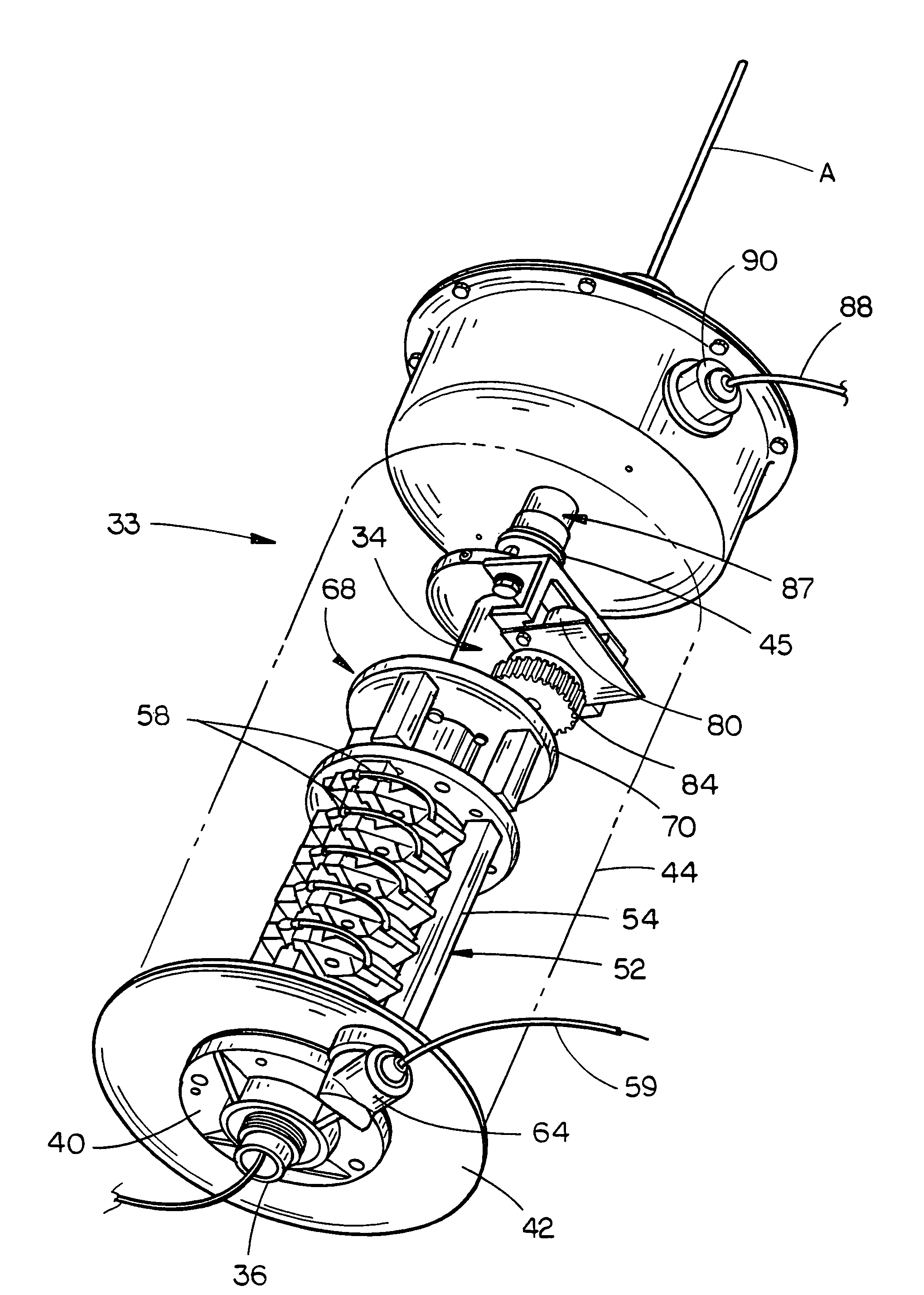
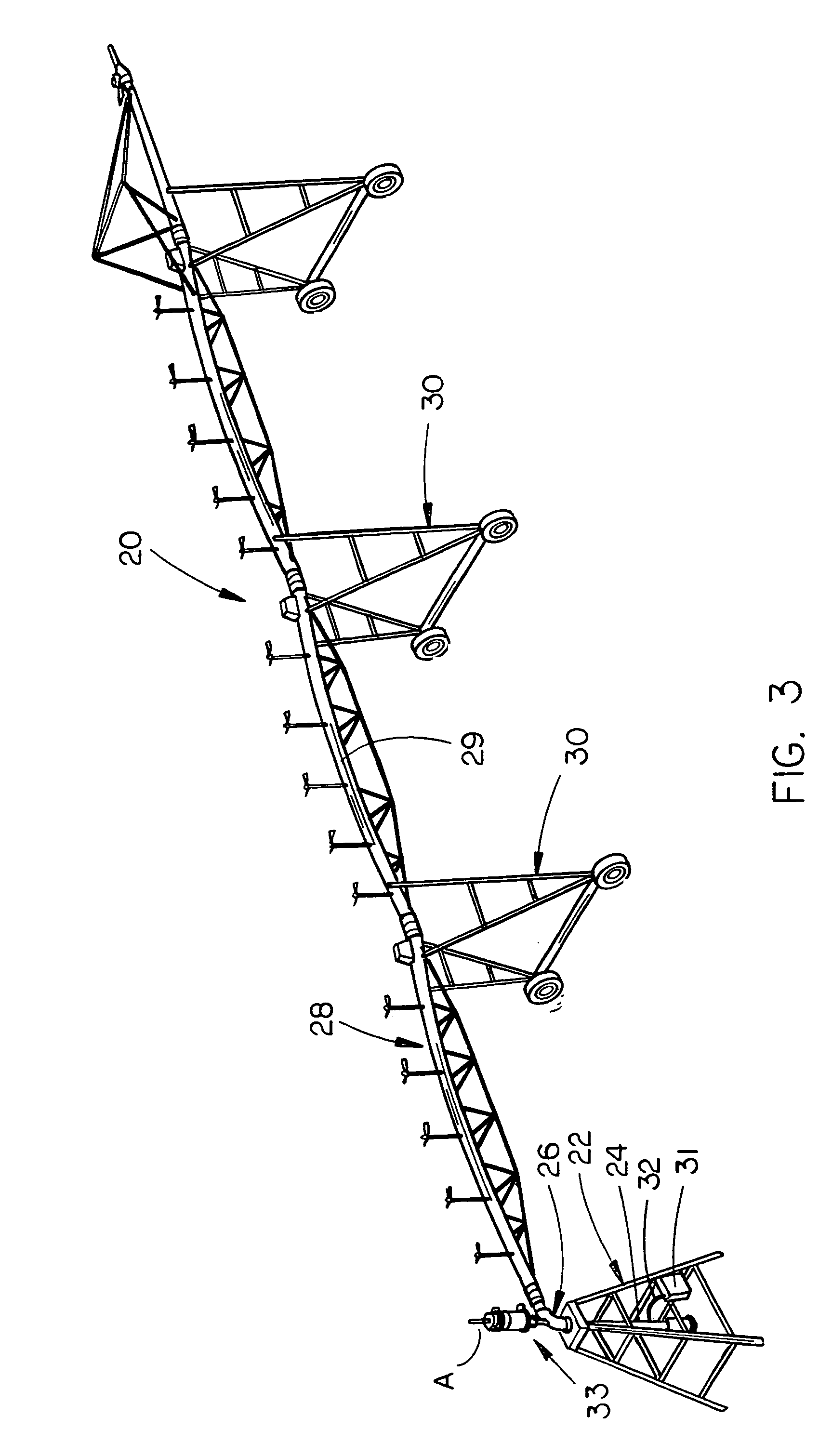
[0026]In FIG. 3, the numeral 20 refers to a generally conventional center pivot irrigation system including a fixed center pivot structure 22 having a vertically disposed water supply pipe 24 provided thereon which is in communication with a source of water under pressure. A conventional swivel 26 is rotatably mounted on the upper end of the water supply pipe 24 and has a span structure 28 secured to the discharge end thereof in conventional fashion. Span structure 28 includes a water delivery pipe 29 supported upon one or more self-propelled drive units 30. Control panel 31 is mounted on the center pivot structure 22 and has a plurality of electrical signal and power wires 32 extending therefrom. The signal wires and power wires extending from the control panel 31 on the center pivot structure 22 extend into the pipe 24 and exit therefrom into a collector ring assembly 33 as will be described hereinafter.

[0027]The numeral 34 refers to an elongated, vertically disposed, hollow mount...


PUM


Abstract

A collector ring for use with a center pivot irrigation system which permits the mounting of a communication device above the span structure. The collector ring also includes a monitoring device which senses the angle or rotation of the span structure with respect to the fixed center pivot structure.

Description

BACKGROUND OF THE INVENTION[0001]1. Field of the Invention[0002]This invention relates to a collector ring for a center pivot irrigation machine which allows the mounting of a communication device above the span structure and / or includes a monitoring device which monitors the angle or rotation of the span structure with respect to the fixed center pivot structure.[0003]2. Description of the Related Art[0004]Due to increasing fuel and labor costs, the demand for remote control of mechanized irrigation systems such as center pivot irrigation systems is increasing. In those situations where the irrigation system includes remote control capabilities, it is necessary for an antenna or other communication device to be mounted at the fixed center pivot structure. One of the limitations associated with the remote control of mechanized irrigation systems is the height at which the antenna or communication device can be mounted at the center pivot structure. The height of the communication de...

Claims


Application Information

Patent Timeline
IPC IPC(8): B05B3/00A01G25/02A01G27/00B67D5/08G05D7/00B67D5/38B05B12/08B67D7/08B67D7/56
CPCA01G25/092
Inventor MALSAM, CRAIG S.SALAZAR, DONALD M.SCHECHINGER, MARK G.NOVOTNY, JOSEPH F.
Owner CONDUCTIX
Why Eureka
Try Eureka