Safety pen needle with passive safety shield system

a safety shield and safety pen technology, applied in the direction of intravenous devices, needles infusion, other medical devices, etc., can solve the problems of needlestick injuries sustained by healthcare workers, needlestick injuries of healthcare workers, and other problems, to achieve the effect of preventing needlestick injuries

Active Publication Date: 2008-12-09
EMBECTA CORP
View PDF22 Cites 66 Cited by
  • Summary
  • Abstract
  • Description
  • Claims
  • Application Information

AI Technical Summary

Benefits of technology

[0010]The sleeve also has hub fastening elements engaging corresponding elements on the hub. Thus, the sleeve engages to the hub in two positions. The sleeve may be temporarily retained on a first retaining element on the hub in a first position, before the injection is administered. This prevents an accidental needlestick until an ample injection force is applied to the endwall of the shield against the patient's body. After the injection is administered, or in the event of an accidental triggering, the hub, sleeve and shield interact to permanently lock out the shield in a protecting position.

Problems solved by technology

Accidental needlestick injuries from contaminated needles expose healthcare workers to the risk of infection from blood-borne pathogens, including the viruses that cause hepatitis B and C, and HIV.
Healthcare workers have sustained needlestick injuries while removing and disposing of pen needles from injection devices after administering an injection to patients.
Needlestick injuries also occur during the removal of pen needles that have not been re-shielded.

Method used


Image

  • Safety pen needle with passive safety shield system
  • Safety pen needle with passive safety shield system
  • Safety pen needle with passive safety shield system

Examples


Embodiment Construction

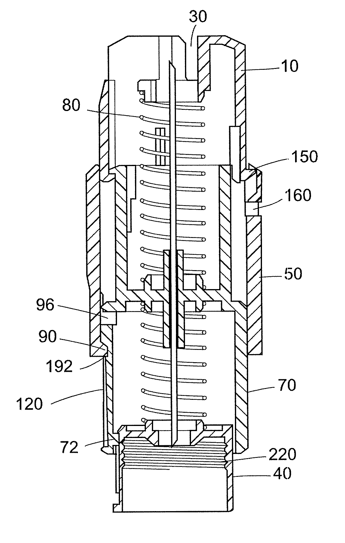
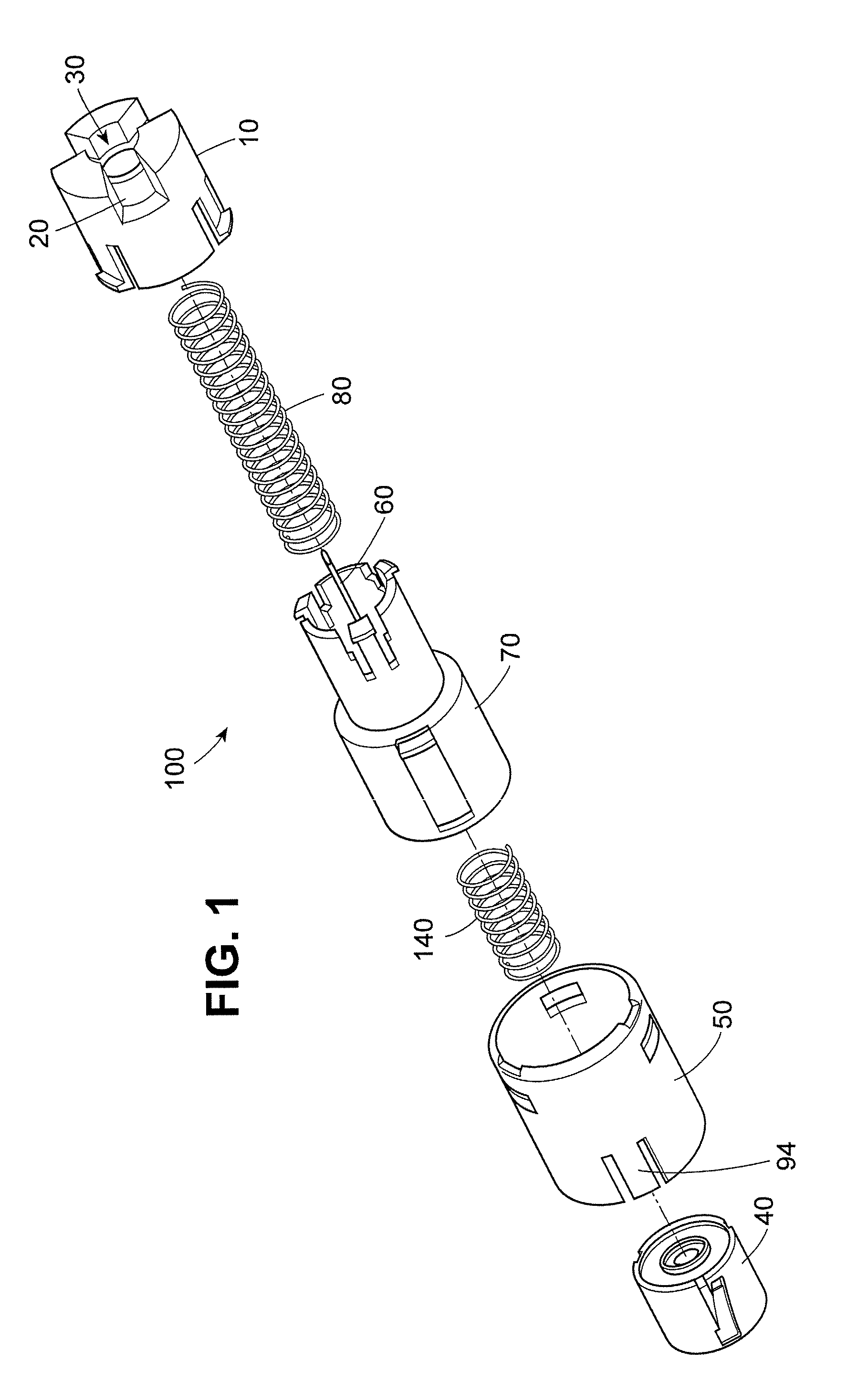
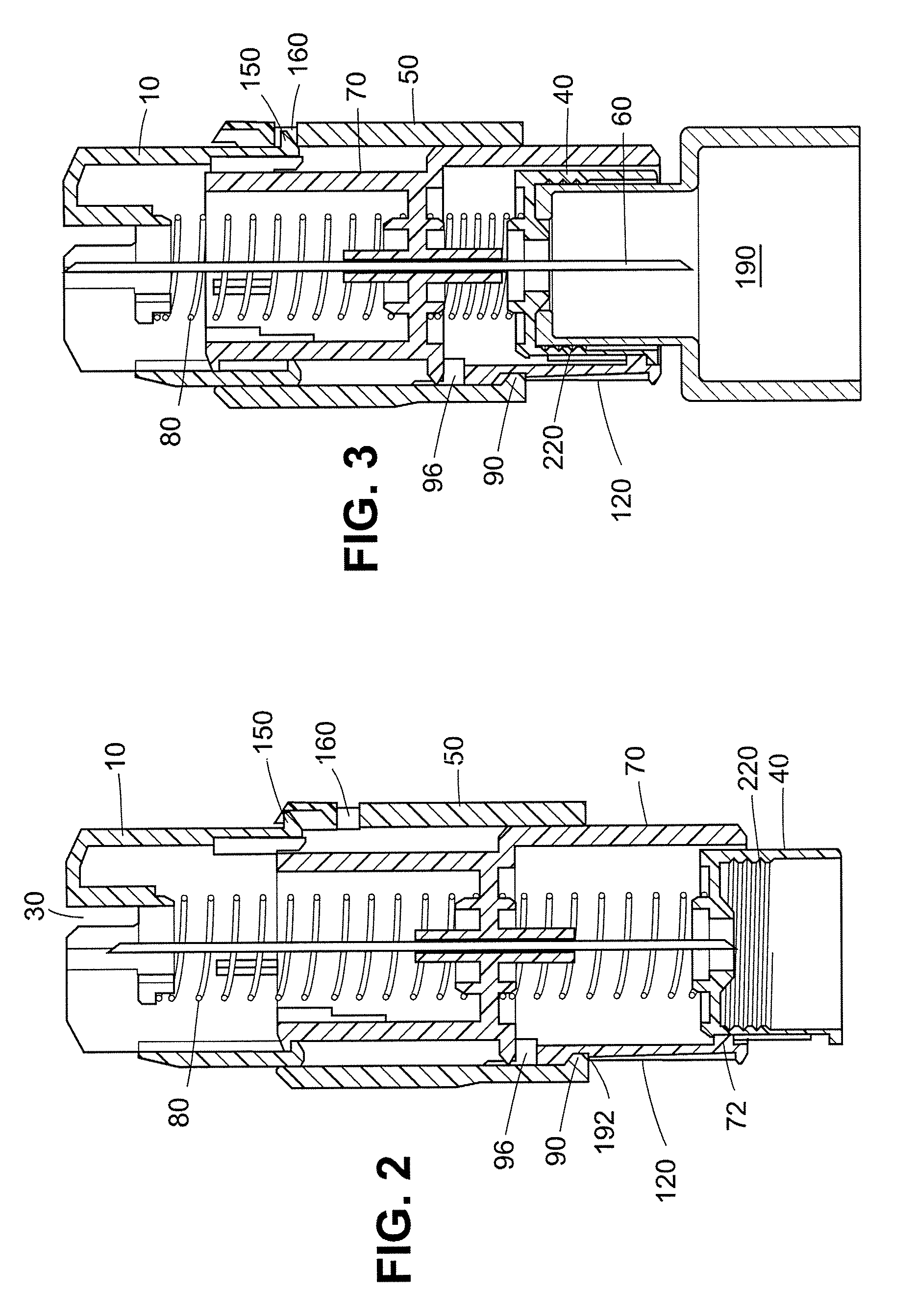
[0022]The safety shield system according to the invention is “passive” because shielding of the injection end of the needle is automatic upon administering an injection, or upon triggering the pen needle in the case of an accidental use. Likewise, shielding of the non-injection end is automatic upon removing the pen-injector. User-implemented steps are not required to shield the needle. The two shields on either side of the needle operate independently, but together constitute a shield “system.” The shield on the injection end cooperates with the sleeve and hub and therefore by itself also constitutes a “system.” The terms “injection end” and “non-injection end” refer to directions on the device. The injection end refers to a direction toward the end of the device that is normally pressed against a patient's body during an injection (the distal end), while the non-injection end refers to the opposite direction, toward the proximal end.

[0023]A pen needle generally has a longest dimen...


PUM


Abstract

A pen needle shield system according to the invention comprises at least an injection end shield positioned on the injection side of the hub, shielding the injection end of the needle after an injection, or in the event of an accidental triggering. The injection end shield is compressed toward the hub against the pressure of a biasing spring. The injection end shield engages a sleeve, which is arranged coaxially on the hub such that after the injection is administered the biasing spring pushes the injection end shield to cover the injection end of the needle, carrying the sleeve with it. The sleeve engages the hub, locking out the injection end shield in a position in which the injection end of the needle is covered by the injection end shield. The system also may incorporate a non-injection end shield that engages with the hub when a pen injector is unscrewed from the hub to lock out the non-injection end shield in the position protecting the non-injection end of the needle.

Description

BACKGROUND OF THE INVENTION[0001]1. Field of the Invention[0002]The invention is directed to a passive safety shield system which may be associated with a pen needle to protect the patient and / or healthcare professional using the pen needle from accidental needlesticks from the injection end and the non-injection end of the needle.[0003]2. Description of the Related Art[0004]Accidental needlestick injuries from contaminated needles expose healthcare workers to the risk of infection from blood-borne pathogens, including the viruses that cause hepatitis B and C, and HIV. According to the Centers for Disease Control and Prevention, healthcare workers in the United States experience an estimated 600,000 exposures to blood each year, with RNs being subject to an overwhelming majority of these incidents.[0005]While the injection device of choice in the U.S. remains the syringe, the demand for pen needles is growing rapidly. The use of self-injection pen needle devices is increasing due to...

Claims


Application Information

Patent Timeline
Patent Type & Authority Patents(United States)
IPC IPC(8): A61M5/32
CPCA61M5/326A61M5/3272A61M5/34A61M2005/3246A61M2039/1027A61M2005/3254A61M2005/3267A61M2205/583A61M2039/1016A61M2005/3247
Inventor STONEHOUSE, DAVID R.LISTENBERGER, ERIC D.
Owner EMBECTA CORP
Why Eureka
Try Eureka