Tire valve unit

a tire valve unit and valve body technology, applied in the direction of tire measurement, vehicle components, transportation and packaging, etc., can solve the problems of affecting the securing of the tire valve unit to the rim, and the securing of the rim of the vehicle, so as to achieve convenient and reliable securing

Active Publication Date: 2008-12-30
PACIFIC INDUSTRIAL CO LTD
View PDF9 Cites 12 Cited by
  • Summary
  • Abstract
  • Description
  • Claims
  • Application Information

AI Technical Summary

Benefits of technology

[0006]Accordingly, it is an objective of the present invention to provide a tire valve unit that can be easily and reliably secured to a rim of a wheel of a vehicle.

Problems solved by technology

However, the hard valve stem, which is arranged radially inward from the elastic cylindrical member, makes it difficult to compress the elastic cylindrical member in a radially inward direction.
This hampers securing of the tire valve unit to the rim.
Further, the rim of a wheel of a vehicle, to which the tire valve unit is secured, receives great shock or vibration caused by traveling of the vehicle.

Method used


Image

  • Tire valve unit
  • Tire valve unit
  • Tire valve unit

Examples


Embodiment Construction

[0013]An embodiment of the present invention will now be described with reference to the attached drawings.

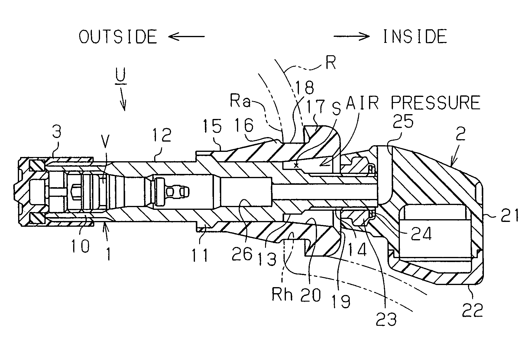
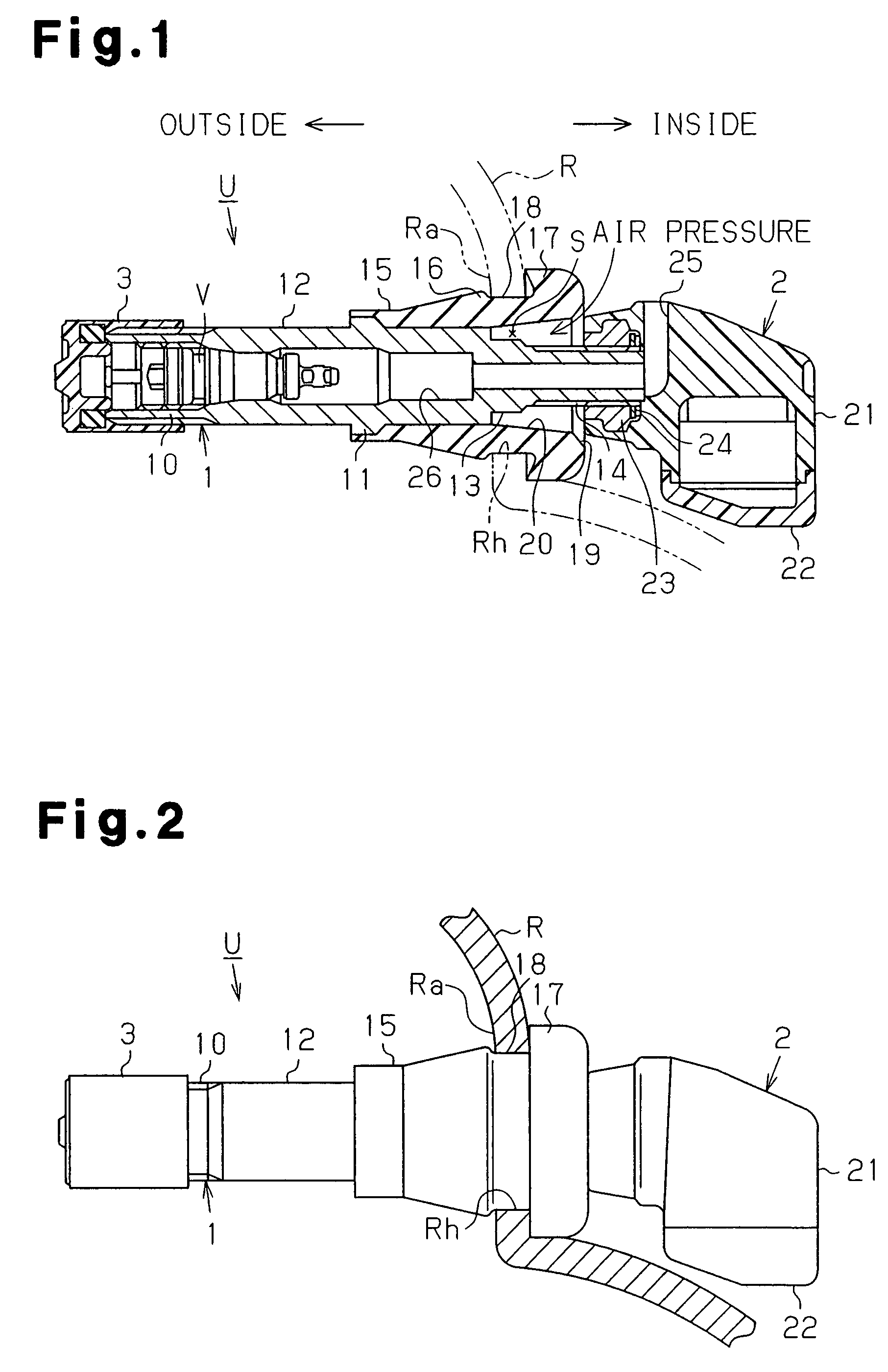
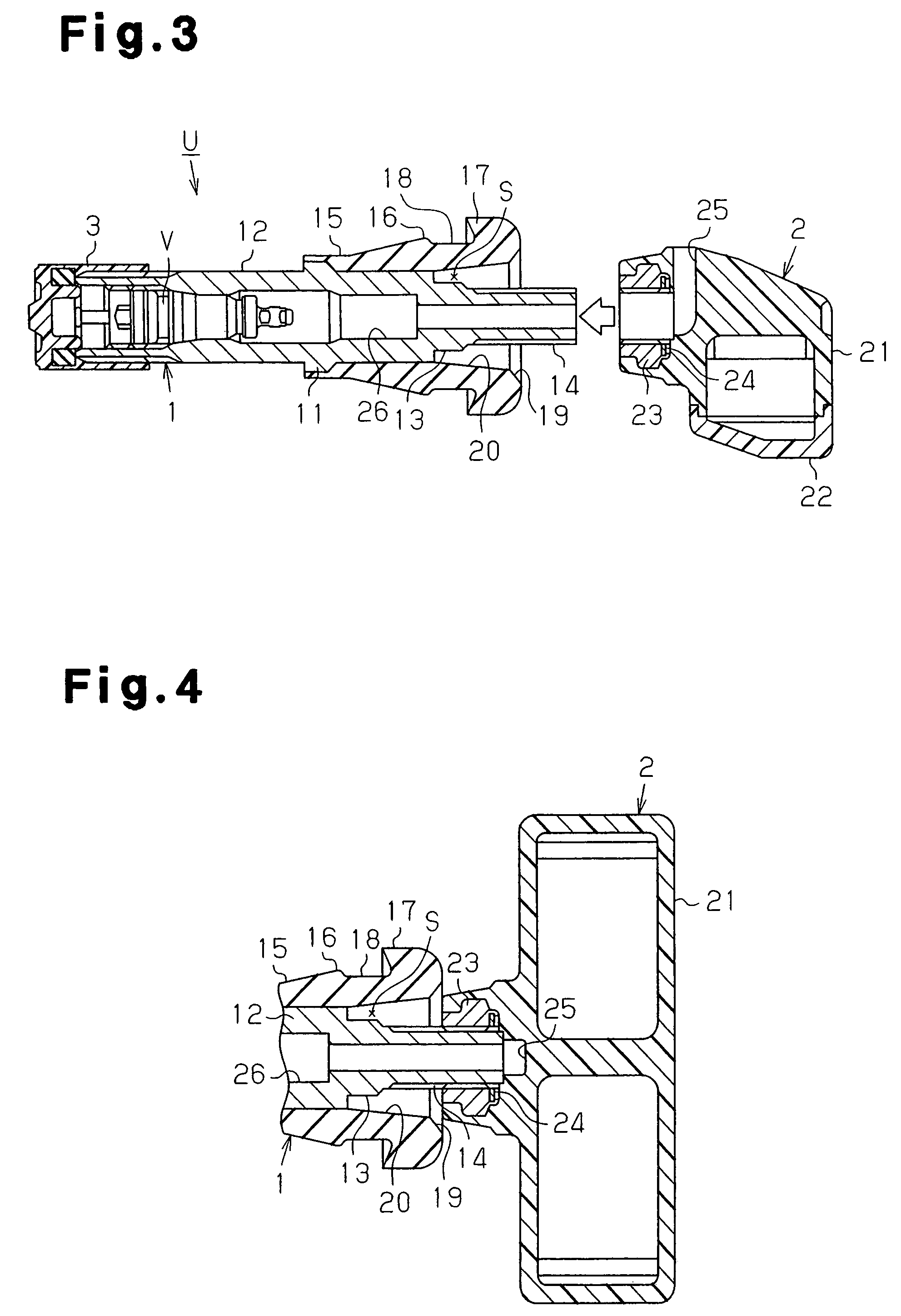
[0014]FIGS. 1 to 3 show a tire valve unit U according to one embodiment of the present invention. The tire valve unit U is used in a tire condition monitoring apparatus that monitors the condition of the tires of a vehicle such as the air pressure or the temperature in the tires. The tire valve unit U includes a tire valve 1 and a tire sensor 2 and is secured to a valve securing hole Rh defined in a rim R of a vehicle wheel.

[0015]The tire valve 1 has a valve body 10 formed of metal. A valve mechanism component V is received in the valve body 10. The valve body 10 includes a cylindrical valve stem 12. Although the valve stem 12 is formed of metal, the valve stem 12 may be formed of resin as long as the valve stem 12 is a hard cylindrical member. The valve stem 12 has a proximal portion located inside the rim R when the tire valve unit U is secured to the rim R. The proximal port...


PUM


Abstract

A tire valve unit is secured to a securing hole provided in a rim of a wheel of a vehicle. The tire valve unit includes a tire valve and a tire sensor. The tire valve includes a valve stem and an elastic cylindrical member encompassing the valve stem. The elastic cylindrical member has an annular securing groove in an outer circumferential surface of the elastic cylindrical member. A portion of the rim around the securing groove is fitted in the securing groove when the elastic cylindrical member is passed through the securing hole. The tire sensor is fixed to the valve stem. The tire sensor is arranged in the interior of a tire attached to the rim and capable of detecting the condition of the tire when the tire valve unit is secured to the rim. The elastic cylindrical member defines an annular space around the valve stem. The annular space extends from a position corresponding to the securing groove in an axial direction of the valve stem to communicate with the interior of the tire.

Description

BACKGROUND OF THE INVENTION[0001]The present invention relates to a tire valve unit that is used in a tire condition monitoring apparatus and has an appropriate securing structure by which the tire valve unit is secured to a rim of a wheel of a vehicle.[0002]A tire condition monitoring apparatus of a vehicle is known. The device allows monitoring of the condition of the tires of the vehicle such as air pressure from the passenger compartment. Various types of tire valve units used in the tire condition monitoring apparatus have been proposed. One such tire valve unit typically includes a tire valve, an elastic cylindrical member, and a tire sensor. The tire valve has a valve body and a valve stem extending from the valve body. The valve stem is a hard cylindrical member formed of metal. The elastic cylindrical member is formed of, for example, rubber and encompasses the valve stem. The tire sensor is, for example, a air pressure sensor and installed in the elastic cylindrical member...

Claims


Application Information

Patent Timeline
Patent Type & Authority Patents(United States)
IPC IPC(8): B60C23/02
CPCB60C23/0408B60C23/0494B60C29/02
Inventor KATOU, MICHIYAHATTORI, YASUAKI
Owner PACIFIC INDUSTRIAL CO LTD
Why Eureka
Try Eureka