Apparatus and method for polishing row bars

a technology of row bars and apparatus, which is applied in the direction of grinding machine components, manufacturing tools, lapping machines, etc., can solve the problems of laborious work, occurrence of defects such as over-cutting, and the apt affect of the surface of the polishing row bar, so as to achieve more precise polishing, easy and reliable secure, and the effect of magnetic head slider

Inactive Publication Date: 2005-06-14
FUJITSU LTD
View PDF5 Cites 5 Cited by
  • Summary
  • Abstract
  • Description
  • Claims
  • Application Information

AI Technical Summary

Benefits of technology

[0008]It is, therefore, an object of the present invention to provide an apparatus and a method for polishing a row bar of magnetic head sliders, capable of controlling the pushing pressure for the individual magnetic head sliders provided in the row bar to precisely polish the row bar.
[0011]In this constitution, the jig comprising the rigid member and the elastic member can be easily and reliably secured to the housing so that it can easily and reliably hold the row bar at a predetermined position. The row bar can be held by the elastic member, by bringing the row bar into intimate contact with the elastic member, even if the row bar is not adhered to the elastic member. The pressing force applied to the elastic member through the holes in the rigid member is transmitted to the row bar to correct the shape of the row bar.
[0013]In this constitution, the jig comprising the rigid member, and the elastic member, can be easily and reliably secured to the housing and the resistance of resistance elements provided in the row bar can be measured in the inprocess condition, whereby the portions of the elastic member corresponding to the magnetic head sliders of the row bar can be individually pressed with variable forces in response to the measured value. The polishing is finished when the target resistance is reached to accomplish more precise polishing.
[0014]In lapping the magnetic head sliders, according to the present invention as described above, it is allowed to control the pressing force for each of the magnetic head sliders in the row bar, and a row bar of any shape can be corrected to be as straight as possible, making it possible to provide magnetic head sliders with good precision. In the apparatus of the static pressure type, in particular, no complex or fine mechanism is employed. Therefore, the unit is assembled through a very decreased number of steps accompanied by very decreased defects. Besides, as compressed air is directly used, dispersion is decreased in the thrust produced through the individual holes, and a highly precise control is accomplished. Besides, the resistance elements in the row bar are connected, by bonding wires, to the terminals of a relay board, to measure the resistance in the inprocess condition, which makes it possible to effect the lapping with high precision.

Problems solved by technology

The row bar is adhered to the elastic member and the positioning of the elastic member is difficult, so laborious work is required for precisely positioning the row bar and, besides, polishing the row bar is apt to be affected by a change in the surface state of the elastic member.
Besides, as the row bar is held by the elastic member, the terminals of resistance elements of the row bar cannot be bonded to the terminals of a measuring device with bonding wires, so the resistance cannot be measured in the inprocess condition and is apt to be affected by the lapping rate, giving rise to the occurrence of defects such as over-cutting.

Method used


Image

  • Apparatus and method for polishing row bars
  • Apparatus and method for polishing row bars
  • Apparatus and method for polishing row bars

Examples


Embodiment Construction

[0029]The preferred embodiments of the present invention will now be described with reference to the drawings.

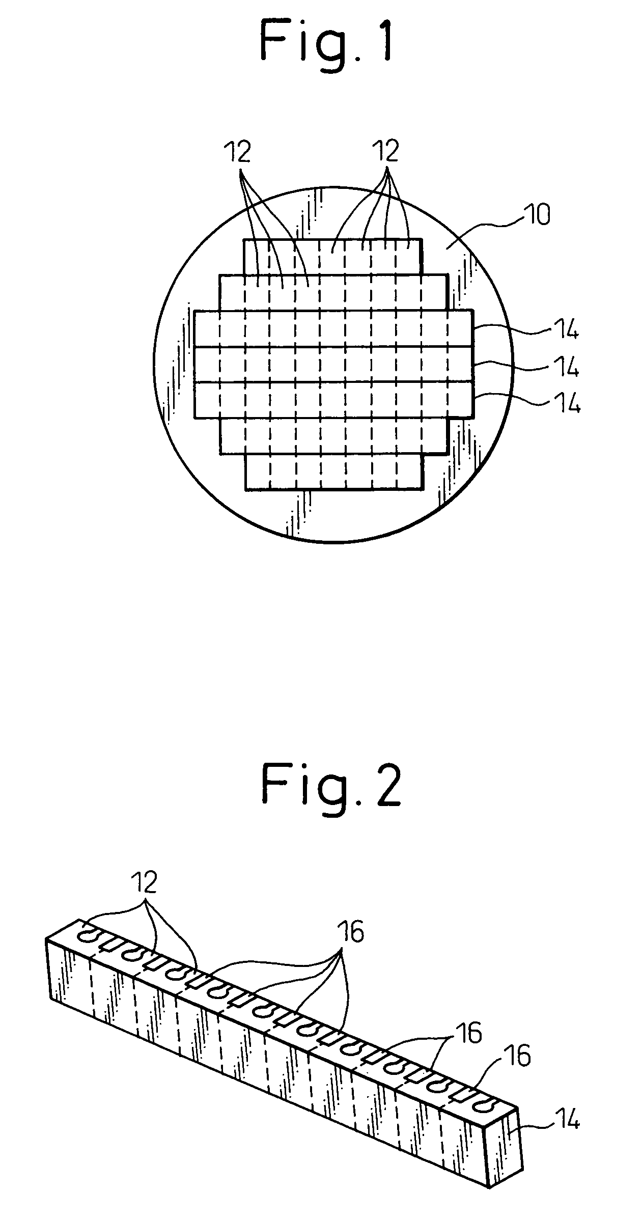
[0030]FIG. 1 is a view illustrating a wafer in which a number of magnetic head sliders are fabricated. The wafer 10 includes many magnetic head sliders 12 fabricated therein by known technology. FIG. 2 is a view illustrating a row bar 14 cut from the wafer 10 of FIG. 1. The row bar 14 includes a plurality of magnetic head sliders (MR heads) 12. An ELG resistance element 16 is provided in a boundary between the two magnetic head sliders 12.

[0031]The surface of the row bar 14 which serves as a floating surface is polished. The row bar 14 is polished through two steps, i.e., an initial polishing (ELG polishing) and a finish polishing (touch lap polishing or crown polishing). The present invention is related to the finish polishing of the row bar 14 after the initial polishing is carried out.

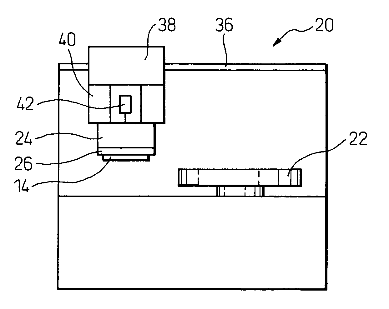
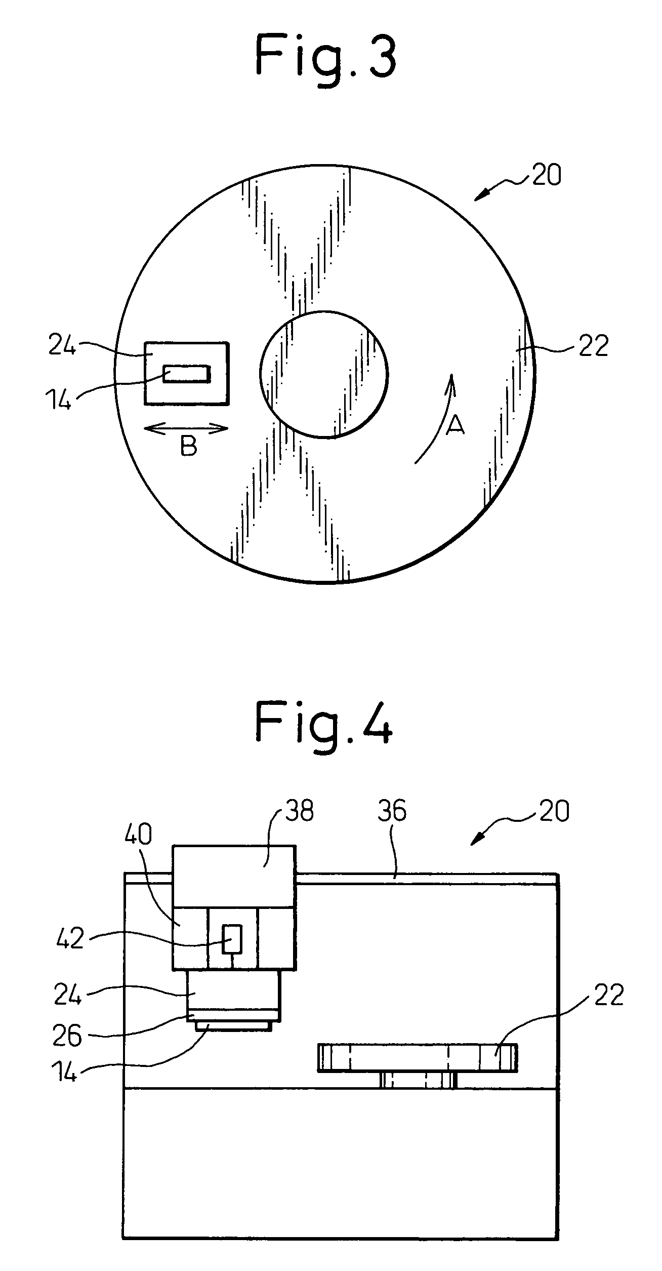
[0032]FIG. 3 is a schematic plan view illustrating a lapping surface plate 22, and a hou...


PUM

PropertyMeasurementUnit
Rockwell hardness HRCaaaaaaaaaa
outer diameteraaaaaaaaaa
diameteraaaaaaaaaa

Abstract

An apparatus and a method for polishing a row bar including magnetic head sliders. A lapping surface plate is rotatable, and a housing is movable above the lapping surface plate. A jig is secured to the housing for holding the row bar. The jig is formed by an elongated rigid member having a plurality of holes and an elongated elastic member fixed to the rigid member. An air cylinder presses the whole row bar, and a pressing devices individually presses portions of the elastic member corresponding to magnetic head sliders of the row bar through the holes of the rigid member. A portion of the elastic member is deformed to press a portion of the row bar in response to a change in the measured resistance of ELG resistance elements in the row bar.

Description

BACKGROUND OF THE INVENTION[0001]1. Field of the Invention[0002]The present invention relates to the production of a magnetic head sliders used in magnetic disk apparatuses. More specifically, the present invention relates to an apparatus for polishing a row bar including magnetic head sliders and to a polishing method.[0003]2. Description of the Related Art[0004]Magnetic head sliders used in the magnetic disk apparatuses are, first, prepared in a large number in the form of a wafer by a film forming technology. The wafer is then cut into row bars including a plurality of magnetic head sliders. The row bars are then polished so that the floating surfaces of the magnetic head sliders become smooth, and are then cut into individual magnetic head sliders.[0005]The row bar is polished through two steps, i.e., an initial polishing (ELG polishing) and a finish polishing (touch lap polishing or crown polishing). The polishing of a row bar is disclosed in, for example, Japanese Unexamined P...

Claims


Application Information

Patent Timeline
Patent Type & Authority Patents(United States)
IPC IPC(8): B24B37/04B24B49/16B24B41/06B24B37/005B24B37/30
CPCB24B37/042B24B49/16B24B41/06
Inventor SUDO, KOJIYANAGIDA, YOSHIAKI
Owner FUJITSU LTD
Why Eureka
Try Eureka