
Abrasive body and method of manufacturing the same

a technology of abrasive bodies and manufacturing methods, which is applied in the direction of gear teeth, gear teeth, gear-teeth manufacturing apparatus, etc., can solve the problems of difficult casting in manufacturing, less than 51% less than 20% of the weight rate of abrasive grains, so as to improve the effect of improving the efficiency of polishing and quality of polished surfaces

Active Publication Date: 2009-05-05
NORITAKE CO LTD
View PDF11 Cites 3 Cited by
  • Summary
  • Abstract
  • Description
  • Claims
  • Application Information

AI Technical Summary

Benefits of technology

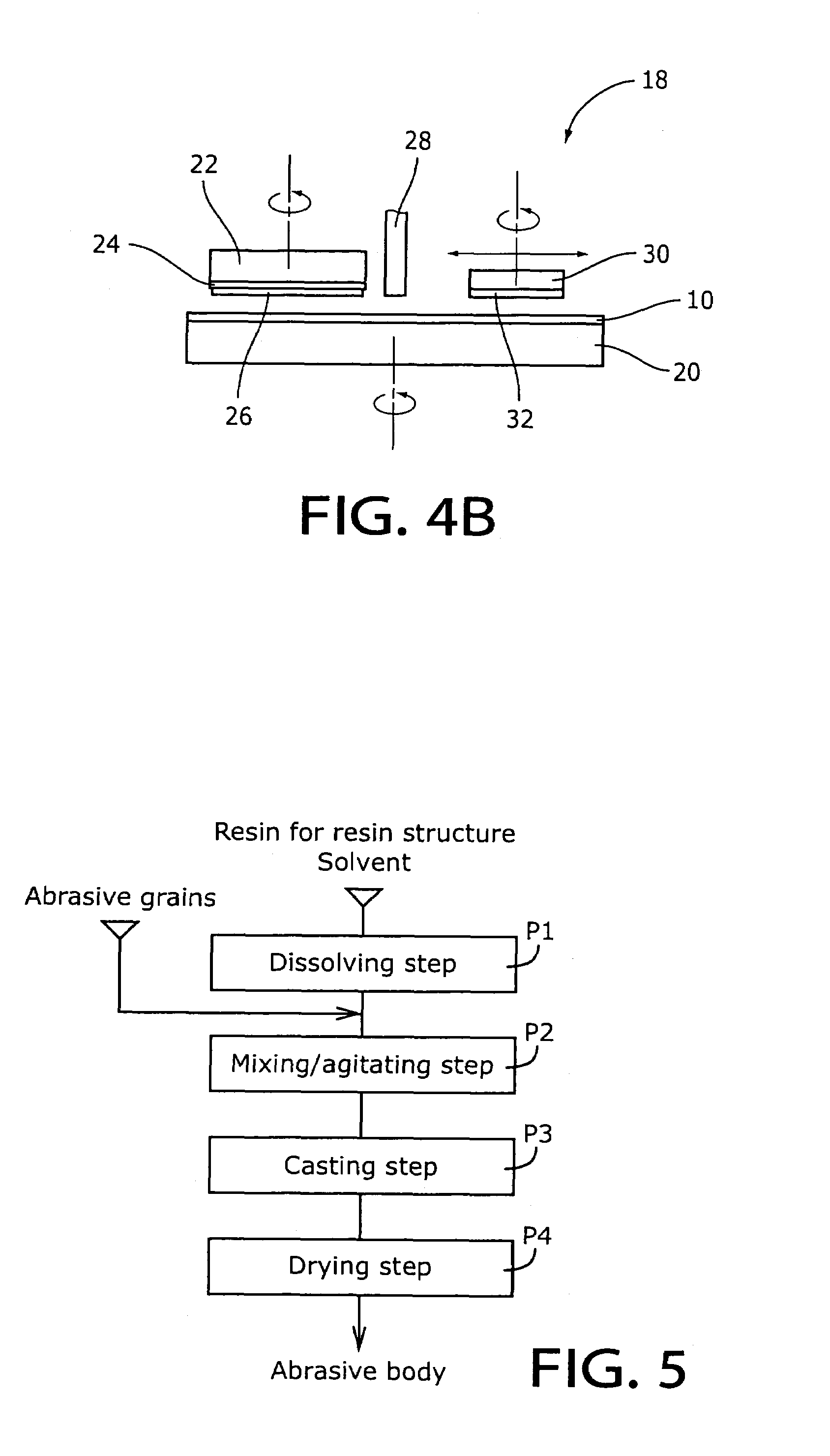
The invention provides an abrasive body for polishing by a Chemical Mechanical Polishing (CMP) method. The abrasive body includes a resin structure made of resin and a plurality of abrasive grains. The resin has a critical surface tension that ranges from 1.6×10⁻² to 4.0×10⁻² N / m. The abrasive grains are likely to remove from the resin structure in polishing by the CMP method because of the bonding strength between them. The abrasive body can supply free abrasive grains between the resin structure and the workpiece. The abrasive grains can be affixed to the internal wall of pores in the resin structure or located apart from the resin structure. The volume rate or weight rate of the abrasive grains in the abrasive body ranges from -20% to 50%. The abrasive body is efficient in polishing and produces a high-quality polished surface without any scratches. The resin structure can be made of resin including at least one material selected from a group of polyvinyl fluoride, vinyl fluoride-hexafluoropropylene copolymer, polyvinylidene fluoride, vinylidene fluoride-hexafluoropropylene copolymer, polyethylene, and polymethyl methacrylate. The abrasive grains can be made of at least one material selected from a group of silicon oxide, cerium oxide, aluminum oxide, zirconium oxide, titanium oxide, manganese oxide, barium carbonate, chromium oxide, and iron oxide. The abrasive body can be made in a form of a disc. The method of manufacturing the abrasive body involves dissolving the resin in a solvent and mixing / agitating it with other materials.

Problems solved by technology

The abrasive body having less than 20% of the volume rate or less than 51% of weight rate of the abrasive grains is inferior in efficiency of polishing and quality of the polished surface.
The abrasive body having over 50% of the volume rate or over 90% of the weight rate of the abrasive grains is difficult of casting in manufacturing.

Method used


Image

  • Abrasive body and method of manufacturing the same
  • Abrasive body and method of manufacturing the same
  • Abrasive body and method of manufacturing the same

Examples


Embodiment Construction

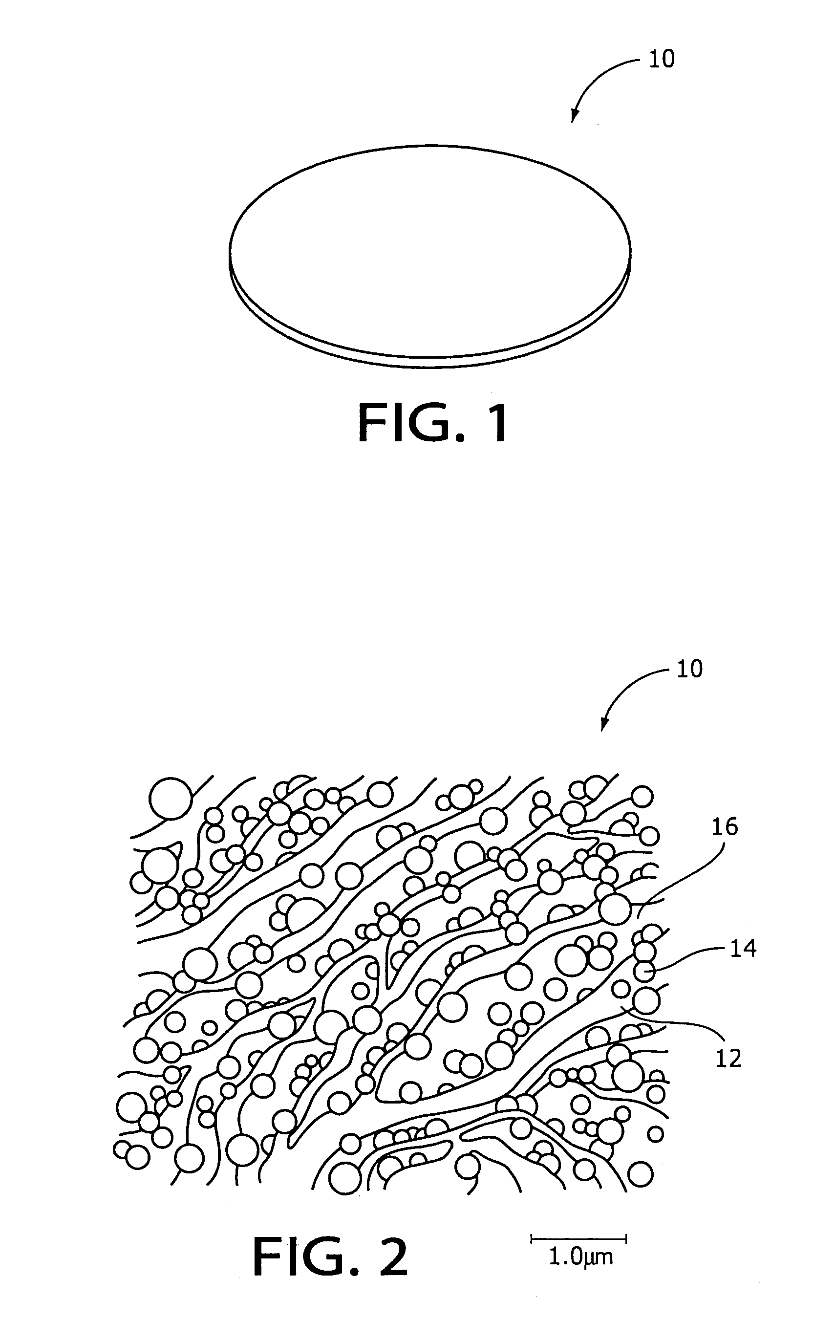
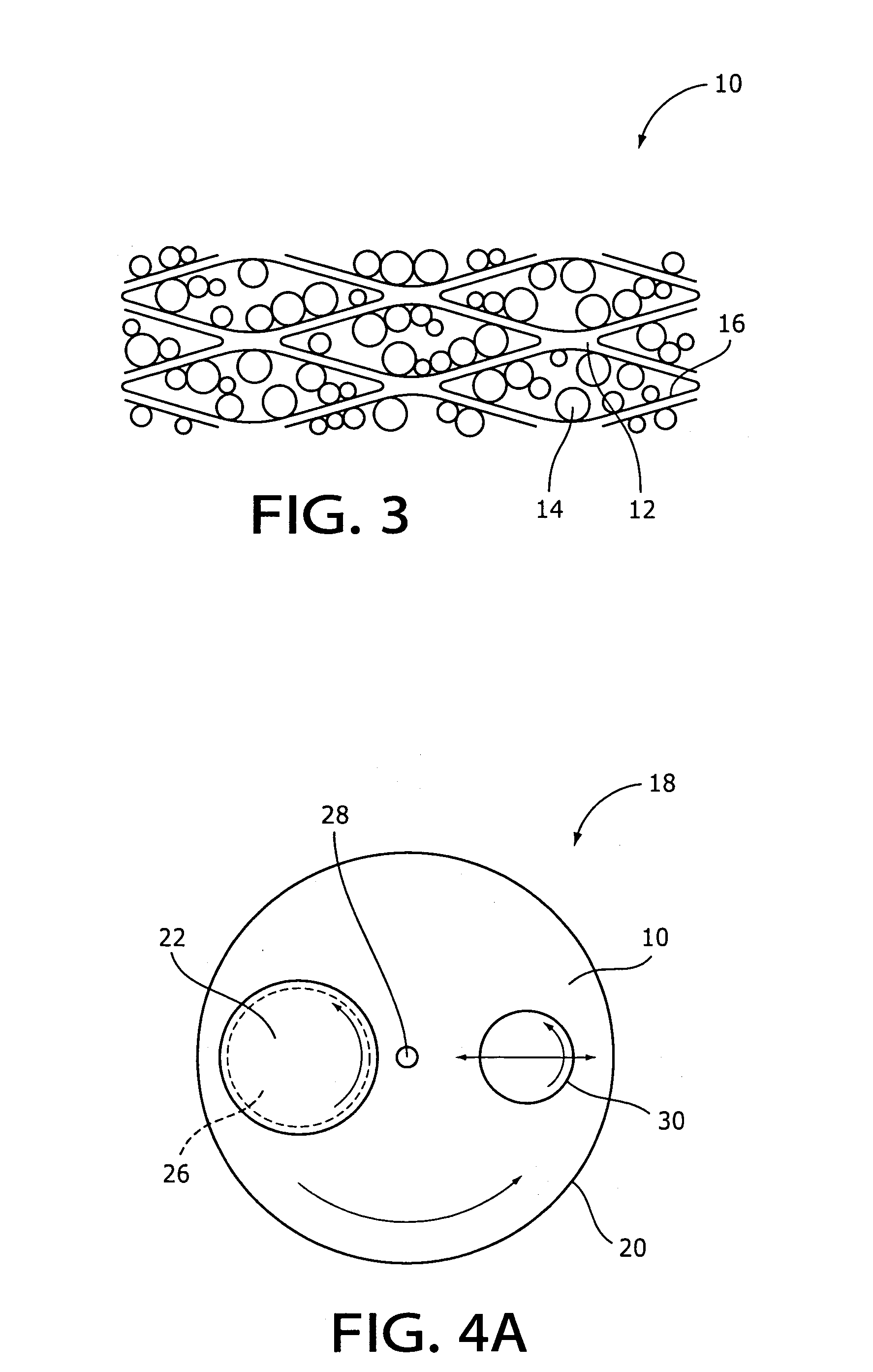
[0025]Hereinafter, there will be described an abrasive body by reference to the drawings. FIG. 1 illustrates an abrasive body 10 in an embodiment according to the invention in a perspective view. As shown in FIG. 1, the abrasive body 10 in the embodiment is provided with a resin structure 12 and a plurality of abrasive grains 14 in a form of disc. The body 10 has the dimensions, for example, of approximately 300 mm in diameter and approximately 5 mm in thickness. The abrasive body 10 is affixed to a polishing table 20 of a polishing apparatus 18 as described below and mostly used for polishing in the CMP method.

[0026]For the resin structure 12 synthetic resin materials of a critical surface tension ranging from 1.6×10⁻² to 4.0×10⁻² N / m are preferably used. The critical surface tension means the surface tension at θ=0, namely, cos θ=1 on an extrapolated line determined on the basis of the plot of the contact angle θ and the surface tension γL of the low-molecular liquid on the surfac...


PUM

PropertyMeasurementUnit
critical surface tensionaaaaaaaaaa
thicknessaaaaaaaaaa
diameteraaaaaaaaaa

Abstract

An abrasive body for polishing includes a resin structure made of resin and a plurality of abrasive grains wherein a critical surface tension of the resin ranges from 1.6×10⁻² to 4.0×10⁻² N / m.

Description

FIELD OF THE INVENTION[0001]The present invention relates to an abrasive body and a method of manufacturing the same for polishing a work piece such as a semiconductor wafer mainly by a Chemical Mechanical Polishing (CMP) method.DESCRIPTION OF RELATED ART[0002]In general, a plurality of chips are formed on a semiconductor wafer and cut them in the terminal step to manufacture the VLSI (Very large scale integration) chips. Late development in VLSI manufacturing technology leads to ultra integration and advanced multilayer interconnection. This demands planarization of the whole surface (global planarization) of the wafer in steps to form each layer. The Chemical Mechanical Polishing (CMP) method is one of the means to realize the planarization of the whole surface of the wafer. In the CMP method the wafer is forcedly rotated being pressed to an unwoven fabric affixed on the polishing table or an polishing pad such as a foam pad, and polishing is proceeded on the wafer receiving a slu...

Claims


Application Information

Patent Timeline
Patent Type & Authority Patents(United States)
IPC IPC(8): B24D3/00B24D3/32B24B37/20B24B37/24B24D3/28B24D3/34B24D7/02H01L21/304
CPCB24B37/245B24D3/32
Inventor SATO, MAKOTO
Owner NORITAKE CO LTD
Learn More