Polishing apparatus

a technology of polishing jigs and jigs, which is applied in the field of polishing jigs, can solve the problems of increasing large storage space, and cumbersome management of them, and achieves the effects of improving the accuracy of finishing, and reducing the manufacturing cost of polishing jigs

Inactive Publication Date: 2005-10-13
HOYA CORP
View PDF6 Cites 4 Cited by
  • Summary
  • Abstract
  • Description
  • Claims
  • Application Information

AI Technical Summary

Benefits of technology

[0023] It is another object of the present invention to provide a polishing apparatus having a polishing jig which can easily replace the polishing pad.
[0024] It is still another object of the present invention to provide a curvature setting apparatus for a polishing apparatus dome portion, a curvature setting method for a polishing apparatus dome portion, and a polishing apparatus, which can measure the curvature of a dome portion suitable for the curvature of a lens more accurately than before.
[0025] It is still another object of the present invention to provide a curvature setting apparatus for a polishing apparatus dome portion, a curvature setting method for a polishing apparatus dome portion, and a polishing apparatus, which can accurately measure the curvature of a dome portion independently of aging of the apparatus.
[0026] It is still another object of the present invention to provide a polishing apparatus, a lens holding tool, and a method of forming a lens holding tool for a polishing apparatus, which increase the accuracy of finishing by reducing deformation of even a thin lens and accordingly increase the accuracy of finishing of the lens.
[0027] It is still another object of the present invention to provide an optical lens polishing method which obtains an accurately polished lens by eliminating a process step formed on the lens at the time of cutting.

Problems solved by technology

This increases the manufacturing cost of polishing jigs.
In addition, a large storage space is necessary, and management thereof is cumbersome.
Such a concave surface cannot be polished by the conventional polishing method using a polishing jig.
When the concave surface is a toric surface, and curvatures in directions perpendicular to each other are largely different, a spherical dome may not be able to cope with such a concave surface.
When the sliding distance for polishing is shortened to keep the lens from the press jig or presser jigs, a large lens cannot be polished.
In this case, the polishing jig becomes bulky.
This also increases the polishing jig size.
If the polishing jig is bulky, the weight and moment of inertia become large.
This may impede the swiveling movement of the polishing jig.
Attaching / detaching the polishing pad is time-consuming.
However, if the deformation amount of the dome portion is large with respect to the pressure variation amount, the pressure is hard to adjust in accordance with the curvature.
Hence, even when the pressure is kept unchanged, no desired curvature can be obtained.
However, since lens materials have high refractive indices, and semifinished lenses become thinner recently, the influence of heat and shrinkage of the alloy layer increases.
Then, the influence of heat and shrinkage of the alloy layer becomes large.
Moreover, the alloy layer of the conventional lens holding tool has a large amount because of the above-described structure that increases the connection strength between the alloy layer and the lens holder unit.
Hence, the influence of heat and shrinkage of the alloy layer is large.
However, even when the amount of alloy is reduced, the influence of heat and shrinkage may still remain because the central thickness of the alloy layer changes depending on the type of lens.
However, when the concave surface of a lens is cut using the curve generator, a process step (undulation) is formed on the cut surface due to backlash.
Even when the turning tool is moved using a linear motor, a similar process step is formed due to, e.g., a delay in control when the moving direction reverses.
However, since the surface must be polished more than necessity, the polishing time becomes long.
In addition, the outer appearance quality and optical accuracy of the lens degrade.

Method used


Image

  • Polishing apparatus
  • Polishing apparatus
  • Polishing apparatus

Examples


first embodiment

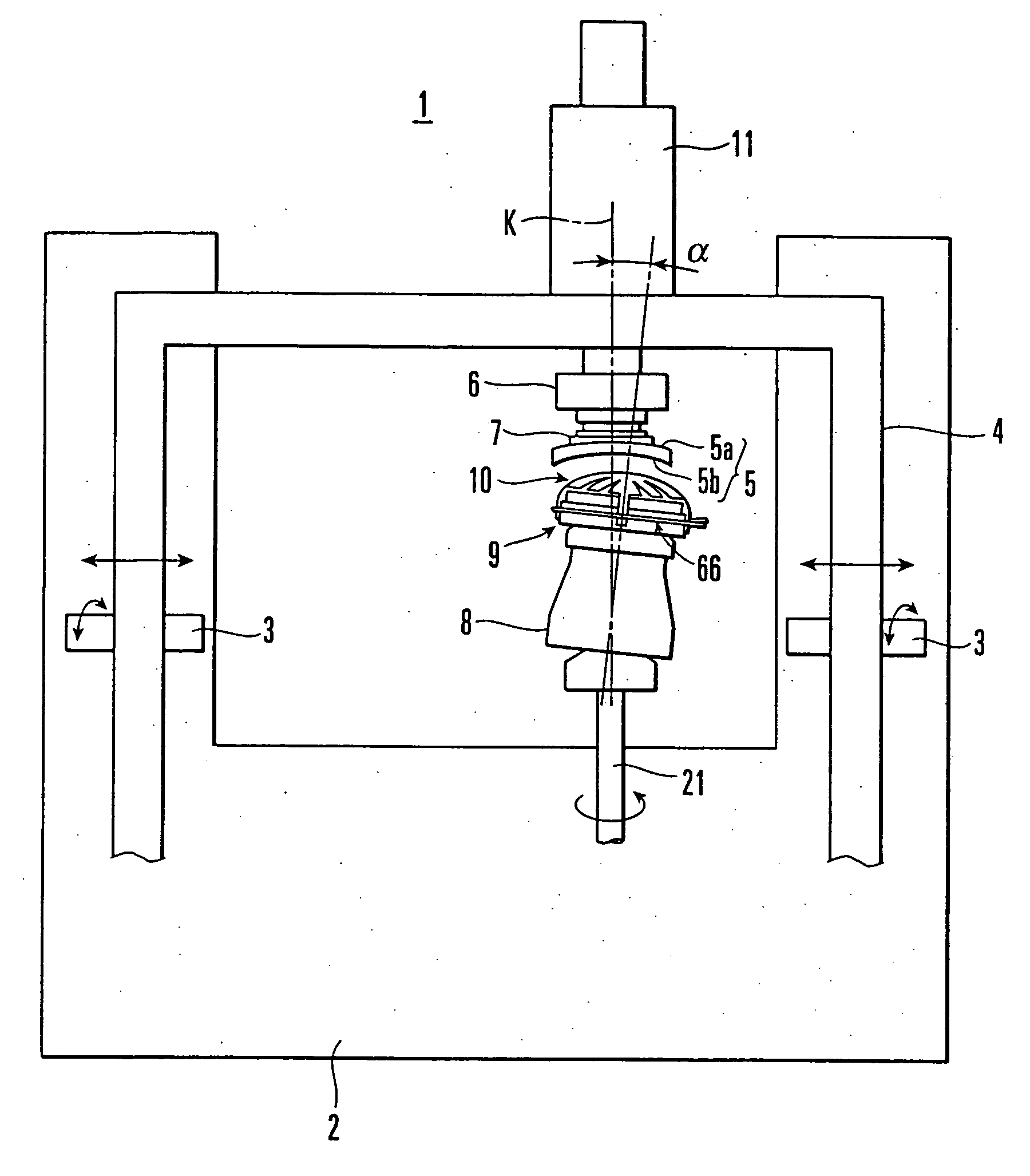
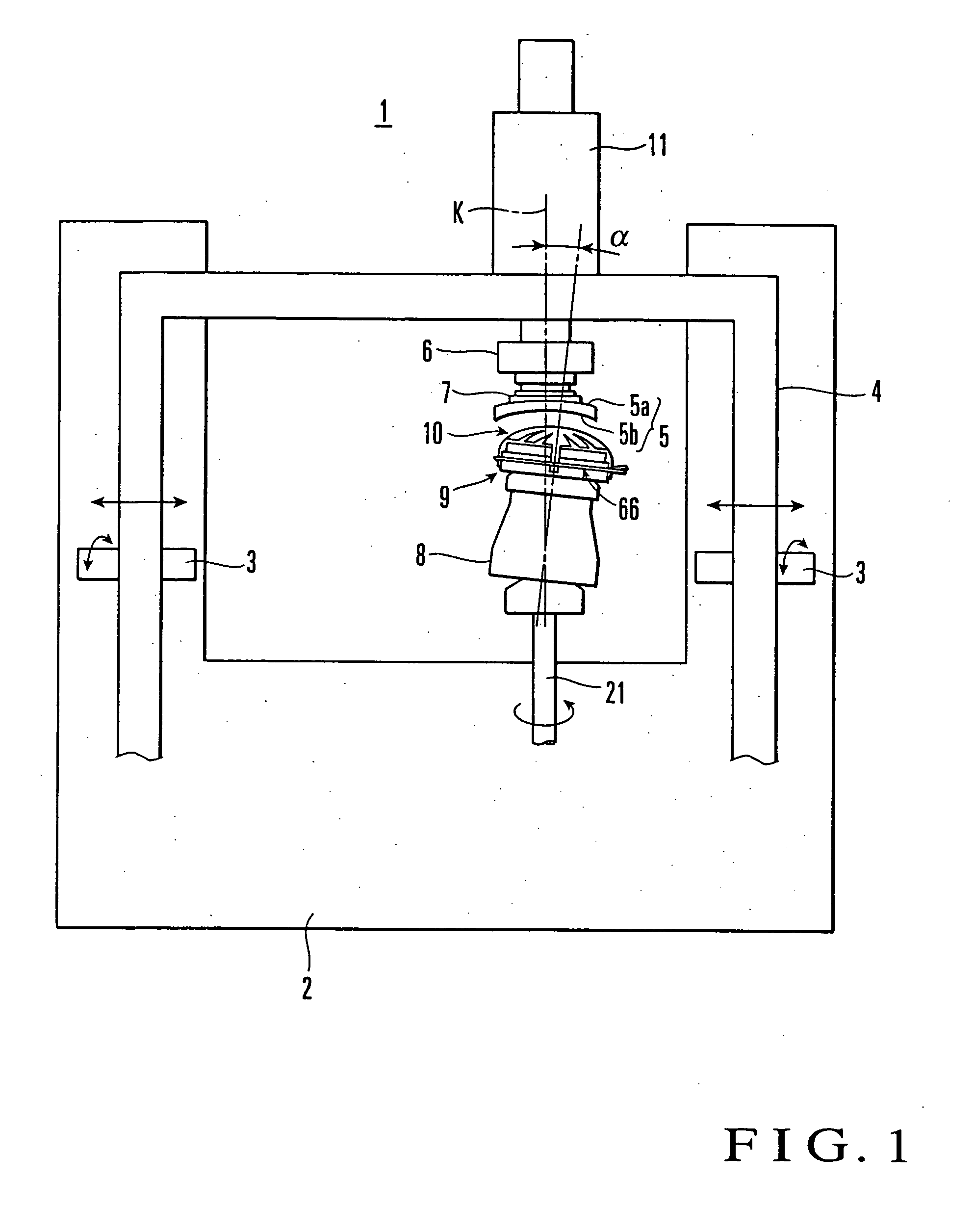
[0067]FIG. 1 shows the basic arrangement of a polishing apparatus according to the present invention. In the embodiment to be described below, the present invention is applied to a polishing apparatus which polishes, as an object to be polished, a concave surface formed from a toric surface of a plastic lens for correcting astigmatism. The lens to be polished is represented by an urethane- or epithio-based plastic lens.

[0068] Referring to FIG. 1, a spectacle lens polishing apparatus 1 comprises an apparatus main body 2 installed on the floor surface, an inverted-U-shaped arm 4 which can freely pivot in a direction perpendicular to the drawing surface about horizontal shafts 3 that are movable to the left and right on the drawing surface, a driving unit (not shown) which reciprocally moves the arm 4 to the left and right and also pivots the arm 4 in the direction perpendicular to the drawing surface, a lens attachment portion 6 which is arranged on the arm 4 to hold a convex surface...

second embodiment

[0116]FIG. 13 shows another embodiment of the present invention.

[0117] In this embodiment, a plate thickness T of a cylinder portion 25B of a balloon member 25 is set to be larger than plate thicknesses T1 and T2 of a dome portion 25A and inner flange 25C. The remaining structures are the same as in the above-described first embodiment.

[0118] In this structure, since the plate thickness T of the cylinder portion 25B is large, and the rigidity increases, the shape holding ability is high. Hence, the dome portion 25A can be stably held, and deformation or expansion / contraction of the cylinder portion 25B due to sliding friction with respect to a lens 5 can be reduced or prevented.

third embodiment

[0119]FIG. 14 shows still another embodiment of the present invention.

[0120] In this embodiment, a balloon member 25 is constructed by a dome portion 25A and cylinder portion 25B. The cylinder portion 25B has, at its rear opening edge, a tapered cylinder portion 25B-1 inclined inward. An annular lock portion 70 bent inward is integrally formed at the end of the tapered cylinder portion 25B-1. The inner flange 25C shown in FIG. 7 is omitted. In addition, an inner fixture 29 and outer fixture 30 have, as their opposing walls, tapered portions 71 and 72 inclined at the same angle as that of the tapered cylinder portion 25B-1. The inner and outer surfaces of the tapered cylinder portion 25B-1 are sandwiched between the tapered portions 71 and 72. The lock portion 70 is fitted in an annular groove 73 formed in the tapered portion 71 of the inner fixture 29, thereby closing the rear opening portion of the balloon member 25. The remaining structures are the same as in the first embodiment...


PUM

PropertyMeasurementUnit
thicknessaaaaaaaaaa
thicknessaaaaaaaaaa
heightsaaaaaaaaaa

Abstract

A polishing apparatus includes a polishing jig. The polishing jig includes an elastic balloon member, a fixture, and a fluid supply portion. The fixture airtightly closes the rear opening portion of the balloon member. The fluid supply portion supplies a fluid into a space formed by the fixture and balloon member. The balloon member has a cup shape constructed by a dome portion and a cylinder portion extending backward from the outer periphery of the dome portion. The fixture fixes the opening portion of the cylinder portion of the balloon member.

Description

BACKGROUND OF THE INVENTION [0001] The present invention relates to a polishing apparatus and, more particularly, to a polishing apparatus which arranges a polishing pad on the outer surface of an elastic dome formed on a base, thereby polishing lenses with various shapes. [0002] Conventionally, to polish, using a polishing apparatus, the concave surface of a lens cut into a spherical or toric surface shape by an NC-controlled curve generator, a polishing pad is bonded to a metal polishing jig having a convex surface almost conforming to the shape of the concave surface to be polished. The polishing jig and lens are relatively slid while pressing the polishing pad against the concave surface to be polished. [0003] In this polishing method, however, various polishing jigs must be prepared in accordance with the shapes of the concave surfaces of lenses to be polished. For, e.g., a toric lens for correcting astigmatism, there are 3,000 to 4,000 kinds of toric surfaces (part of a surfac...

Claims


Application Information

Patent Timeline
Patent Type & Authority Applications(United States)
IPC IPC(8): B24B13/02B24B49/00
CPCB24B13/005B24B13/0052B24B49/00B24B13/012B24B13/02B24B13/01
Inventor TOYOSHIMA, YOSHIAKITORIUMI, HIDEOTAGUCHI, SHIN-ICHIRO
Owner HOYA CORP
Why Eureka
Try Eureka