Polishing pad and methods for manufacturing and using the same

a technology of abrasive blocks and a manufacturing method, which is applied in the field of can solve the problems of low utilization ratio of slurry, poor polishing, environmental pollution, etc., and achieve the effects of complementing the polishing effect, reducing the height of the abrasive blocks with the biggest height, and reducing the polishing ra

Inactive Publication Date: 2012-07-26
SEMICON MFG INT (SHANGHAI) CORP
View PDF27 Cites 4 Cited by
  • Summary
  • Abstract
  • Description
  • Claims
  • Application Information

AI Technical Summary

Benefits of technology

[0028]The polishing pad according to the embodiments of the present invention has a plurality of abrasive blocks fixed thereon which are of at least two kinds of heights. When polishing a wafer, the height of the abrasive blocks having the biggest height is lowered by polishing exhaustion, which degrades the polishing rate. Afterwards, the abrasive blocks having the second biggest height can complement the polishing efficacy, thereby stabilizing the polishing rate, which facilitates to control a thickness of the wafer to be polished accurately and to improve the effect and yield of polishing.

Problems solved by technology

In the conventional CMP process, the polishing slurry distributes randomly on the polishing pad, which induces lots of negative problems such as an uneven density, a poor polishing result, a low utilization ratio of the slurry, and environmental pollution caused by wasted polishing slurry.
However, the polishing rate is continuously becoming slower as the polishing process is going on.
Referring to FIG. 2, the polishing rate descends rapidly from about 1050 Å / min within the first 60 s to about 190 Å / min within a time period from 180 s to 240 s. A thickness of the wafer to be polished is difficult to be controlled accurately because the polishing rate drops rapidly, which causes over-polishing or insufficient polishing leading to wafer damaged.

Method used


Image

  • Polishing pad and methods for manufacturing and using the same
  • Polishing pad and methods for manufacturing and using the same
  • Polishing pad and methods for manufacturing and using the same

Examples


first embodiment

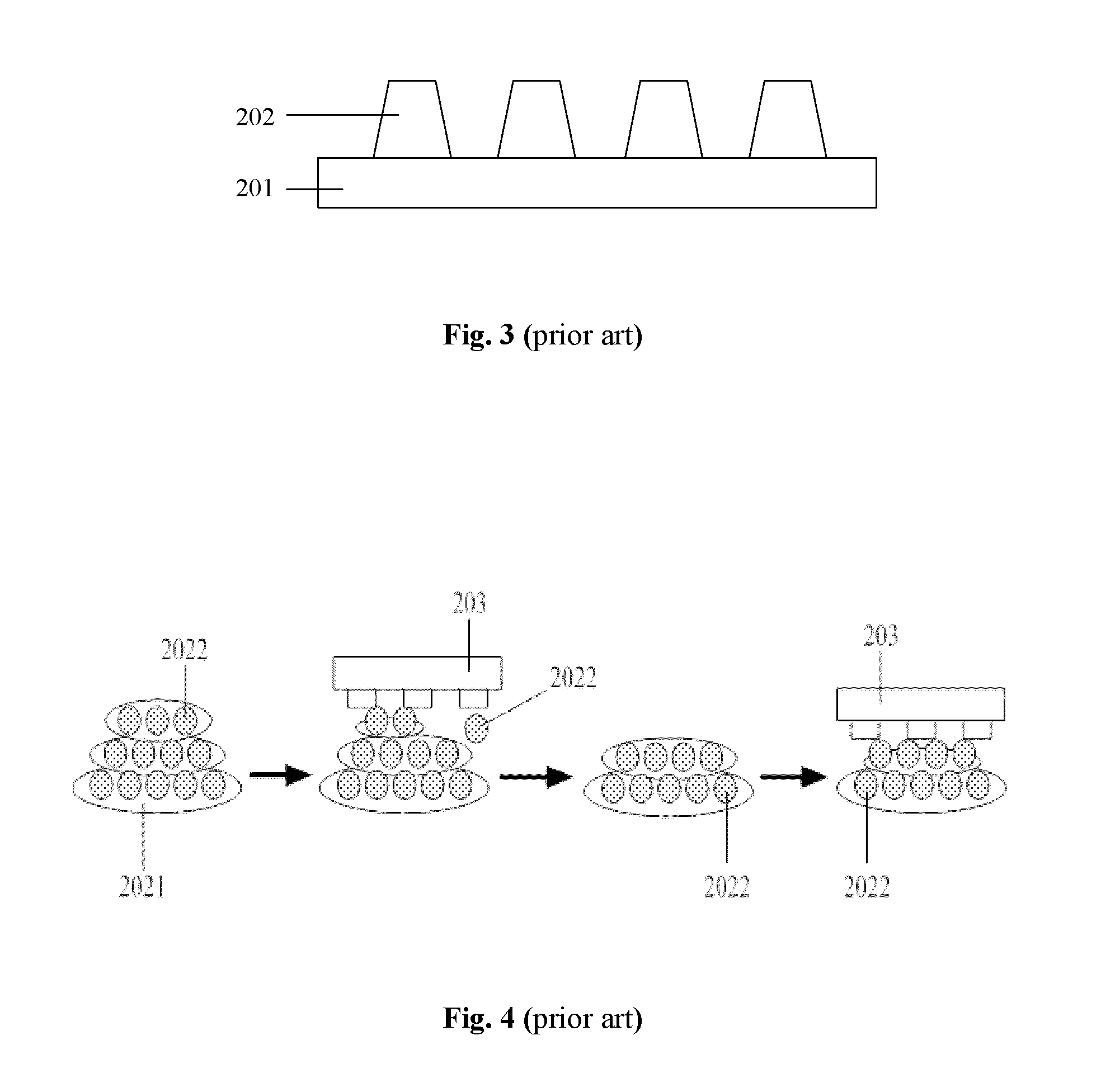
[0040]FIG. 5 is a cross-sectional view of a polishing pad according to the present invention. Referring to FIG. 5, the polishing pad includes a substrate 301 and a plurality of abrasive blocks 302 fixed on the substrate 301. The abrasive blocks 302 are of two kinds of heights, which include abrasive blocks 3021 having a first height h1 and abrasive blocks 3022 having a second height h2. The first height h1 is from about 3 μm to about 5 μm greater than the second height h2. The first height h1 and the second height h2 may be ranging from about 10 μm to about 50 μm, preferably, the first height h1 may be about 30 μm. A width of the abrasive blocks 302 having the first height h1 and the second height h2 may be from about 50 μm to about 200 μm, preferably, the width may be about 100 μm

[0041]In this embodiment, the abrasive blocks 302 having different heights may be arranged from highest to lowest height, from lowest to highest height, or alternating high and low height on the substrate ...

second embodiment

[0048]FIG. 6 is a cross-sectional view of a polishing pad according to the present invention. Referring to FIG. 6, a polishing pad includes a substrate 301 and a plurality of abrasive blocks 302 fixed on the substrate 301. The abrasive blocks 302 are of more than two kinds of heights, which include a first height h1, a second height h2, . . . , a nth height hn (n is a natural number from 3 to 20). The height hn of the abrasive blocks 302 may be ranging from about 10 μm to about 50 μm. A height difference between any two kinds of the abrasive blocks 302 is at least from about 3 μm to about 5 μm. In other words, the absolute value of the difference between the height hn and the height hi (i is not equal to n, and i is a natural number from 3 to 20) is from about 3 μm to about 5 μm. A width W of the abrasive blocks 302 may be from about 50 μm to about 200 μm.

[0049]In this embodiment, the substrate 301 includes materials as described in the first embodiment. The materials and shapes of ...

third embodiment

[0054]FIG. 7 to FIG. 10 schematic diagrams illustrating a method for manufacturing a polishing pad according to the present invention. Referring to FIG. 7, a substrate 301 is provided, and coated uniformly with a mixture 3021 comprising a plurality of abrasive particles and resin adhesives.

[0055]In this embodiment, the substrate 301 may be a rigid substrate, such as a substrate comprising organic glass (PMMA), polyvinyl chloride (PVC), polycarbonate (PC), polyethylene terephathalate (PET), and the like. Optionally, the substrate 301 may be a resilient substrate, which includes polyurethane, polyolefin, phenylethylene, polyester, polyamide, black damping cloth, and the like. Optionally, the substrate 301 may be a multilayer substrate which is formed by combining the rigid substrate with the resilient substrate.

[0056]In this embodiment, the abrasive particles may include one or more materials selected from silicon dioxide, cerium dioxide, aluminium oxide, silicon carbide, boron carbid...


PUM

PropertyMeasurementUnit
heightsaaaaaaaaaa
heightsaaaaaaaaaa
widthaaaaaaaaaa

Abstract

This invention provides a polishing pad, which includes a substrate and a plurality of discrete abrasive blocks fixed on the substrate, wherein the abrasive blocks are of at least two kinds of heights. This invention would not reduce the polishing rate dramatically during the process for polishing a wafer by using the polishing pad in the long run. Therefore a thickness of the wafer to be polished is able to be controlled accurately, thereby improving the effect and yield of polishing the wafer. The present invention further provides a method for manufacturing the polishing pad. The polishing pad according to this invention is manufactured conveniently by using this method. Correspondingly, a method for using the polishing pad is also provided in this invention.

Description

CROSS REFERENCE TO RELATED APPLICATIONS[0001]The present application claims the priority of Chinese Patent Application No. 201110023424.6, entitled “Polishing Pad and Methods for Manufacturing and Using the same”, and filed on Jan. 20, 2011, the entire disclosure of which is incorporated herein by reference.FIELD OF THE INVENTION[0002]The present invention relates generally to semiconductor manufacturing process, and more particularly to a polishing pad and methods for manufacturing and using the same.BACKGROUND OF THE INVENTION[0003]In semiconductor manufacturing process, it is quite important for a device capable of being miniaturized and highly integrated to have a smooth wafer surface. Generally speaking, chemical mechanical polishing (CMP) is used as a conventional process for planarizing a wafer surface. A polishing slurry is added between the wafer surface and a polishing pad. By the effects of mechanical force and the chemical reaction generated between the wafer surface and...

Claims


Application Information

Patent Timeline
Patent Type & Authority Applications(United States)
IPC IPC(8): B24B1/00B24D18/00B24D3/28B24D11/00
CPCB24B37/16
Inventor SHAO, QUN
Owner SEMICON MFG INT (SHANGHAI) CORP
Why Eureka
Try Eureka