
Variable-parameter crank shaft corrective polishing method and device

A crankshaft correction and polishing device technology, which is applied in the direction of grinding/polishing equipment, grinding machines, metal processing equipment, etc., can solve the problem that journal rounding and journal side polishing are difficult to implement, and journal roundness error correction and roundness cannot be corrected. Errors and other problems, to achieve the effect of reducing time, high processing efficiency, and improving processing efficiency

Inactive Publication Date: 2013-06-19
NEIJIANG FUSHENG MACHINERY
View PDF6 Cites 4 Cited by
  • Summary
  • Abstract
  • Description
  • Claims
  • Application Information

AI Technical Summary

Problems solved by technology

[0002] In the production process of the crankshaft, journal polishing is a very important process, which directly affects the performance of the product. The existing polishing machines include machine tools for driving the crankshaft, follow-up clamping devices, and follow-up clamps. The two polishing heads on the holding device, the abrasive belt between the two polishing heads, the two polishing heads are symmetrically arranged on both sides of the crankshaft journal and are driven by the crankshaft journal to reciprocate and swing; the device only It can be used to improve the surface roughness of the journal, but it is impossible to correct the roundness error of the journal, and it is difficult to perform the polishing of the fillet of the journal and the side of the journal; and in the machining and forming of the journal, no matter what method is used to grind The journal will always produce different degrees of roundness errors, especially in the processing of large crankshafts, and the journals are more likely to have roundness errors. Although the errors are very small, for the machining of journals, the roundness error The smaller the better, some workpieces cannot be re-ground on the grinding machine due to the small error of the roundness, and must be processed to the required size, which becomes a big processing problem, which cannot be overcome by the existing polishing equipment ; How to improve the surface roughness of the journal in the polishing process, and at the same time effectively correct the roundness error of the crankshaft journal and polish the fillet of the journal and the two sides of the thrust journal, has always been a research topic in the crankshaft processing industry

Method used


Image

  • Variable-parameter crank shaft corrective polishing method and device
  • Variable-parameter crank shaft corrective polishing method and device
  • Variable-parameter crank shaft corrective polishing method and device

Examples


Embodiment Construction

[0013] The present invention will be described in further detail below in conjunction with the accompanying drawings.

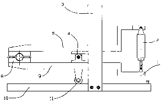
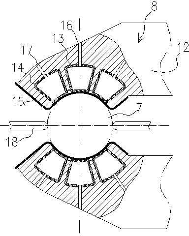
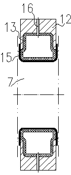
[0014] Such as Figure 1 to Figure 3 As shown, the variable parameter crankshaft correction polishing device includes a machine tool (not shown, such as a lathe) that drives the crankshaft to rotate, a follow-up clamping device 1, and two polishing heads 8 arranged on the follow-up clamping device 1, The follow-up clamping device 1 includes an upper pressing arm 5, a lower pressing arm 9, an oil cylinder 2, a guide rail 10 and a stop frame 3. The upper pressing arm 5 and the lower pressing arm 9 are hinged in the middle by a pin 4, and the two ends of the oil cylinder 2 are respectively Hinged with the rear ends of the upper pressing arm 5 and the lower pressing arm 9, the lower pressing arm 9 is equipped with a roller 11 cooperating with the guide rail 10, the stop frame 3 is in an inverted U shape, and its two ends are fixed on both sides of the guide rail ...


PUM


Abstract

The invention discloses a variable-parameter crank shaft corrective polishing method and a device. The variable-parameter crank shaft corrective polishing device comprises a machine tool which drives a crank shaft to rotate, a servo holding device and two polishing pressure heads, wherein each polishing pressure head comprises a base seat, at least two polishing air bags which are fixedly connected in the base seat and a pressurization air bag. The pressurization air bag is located between the polishing air bags, outer ends of the air bags are all located outside the self base seat and are arranged in an arc shape, the outer end faces of the outer ends are all in arc shapes, the base seats are both fixedly connected with abrasive belts, the polishing air bags are connected with a polishing air source, and the pressurization air bags are connected with the polishing air source and a corrective air source through an automatic control valve on external pipelines. A roundness detection sensor is further arranged on the servo holding device or the two polishing pressure heads, the machine tool is provided with a rotation speed sensor, and the auto control valve, the roundness detection sensor and the rotation speed sensor are all connected with an industrial control machine. According to the variable-parameter crank shaft corrective polishing method and the device, not only can the roundness error of a shaft neck of the crank shaft be accurately corrected and polished, but also a crank shaft neck round angle and two side faces of a thrust shaft neck can be polished, and the machining efficiency is high.

Description

technical field [0001] The invention relates to a method and device for correcting and polishing a crankshaft. Background technique [0002] In the production process of the crankshaft, journal polishing is a very important process, which directly affects the performance of the product. The existing polishing machines include machine tools for driving the crankshaft, follow-up clamping devices, and follow-up clamps. The two polishing heads on the holding device, the abrasive belt between the two polishing heads, the two polishing heads are symmetrically arranged on both sides of the crankshaft journal and are driven by the crankshaft journal to reciprocate and swing; the device only It can be used to improve the surface roughness of the journal, but it is impossible to correct the roundness error of the journal, and it is difficult to perform the polishing of the fillet of the journal and the side of the journal; and in the machining and forming of the journal, no matter ...

Claims


Application Information

Patent Timeline
Patent Type & Authority Applications(China)
IPC IPC(8): B24B21/02B24B21/18
Inventor 张雄伟
Owner NEIJIANG FUSHENG MACHINERY
Learn More