Method of processing sounds from stringed instrument and pickup device for the same

a stringed instrument and sound processing technology, applied in the field of sound processing methods and pickup devices for the same, can solve the problems of difficult mounting of the sensor, inability to pick up the vibration of the top plate, and inability to achieve tone. inappropriate,

Inactive Publication Date: 2005-04-28
KIYOHIKO YAMAYA
View PDF6 Cites 14 Cited by
  • Summary
  • Abstract
  • Description
  • Claims
  • Application Information

AI Technical Summary

Benefits of technology

[0030] In a sound processing method and a pickup device for a stringed instrument according to the present invention, a vibration sensor section is mounted on a fixing member of a stringed instrument such as a guitar so that the vibration

Problems solved by technology

The pickup device is therefore very useful in electrically expanding instrument sounds but has the problems described below.
It is thus difficult to pick up the vibration of the top plate, which is characteristic of the tone of the acoustic guitar.
Therefore, mounting the sensor is difficult.
With this pickup device, picked-up sounds have certain peculiarities and the tone is thus inappropriate because the top plate has complicated vibration characteristics.
Furthermore, when such a stuck type pickup device is removed, varnish ma

Method used


Image

  • Method of processing sounds from stringed instrument and pickup device for the same
  • Method of processing sounds from stringed instrument and pickup device for the same
  • Method of processing sounds from stringed instrument and pickup device for the same

Examples


embodiment 1

[Embodiment 1]

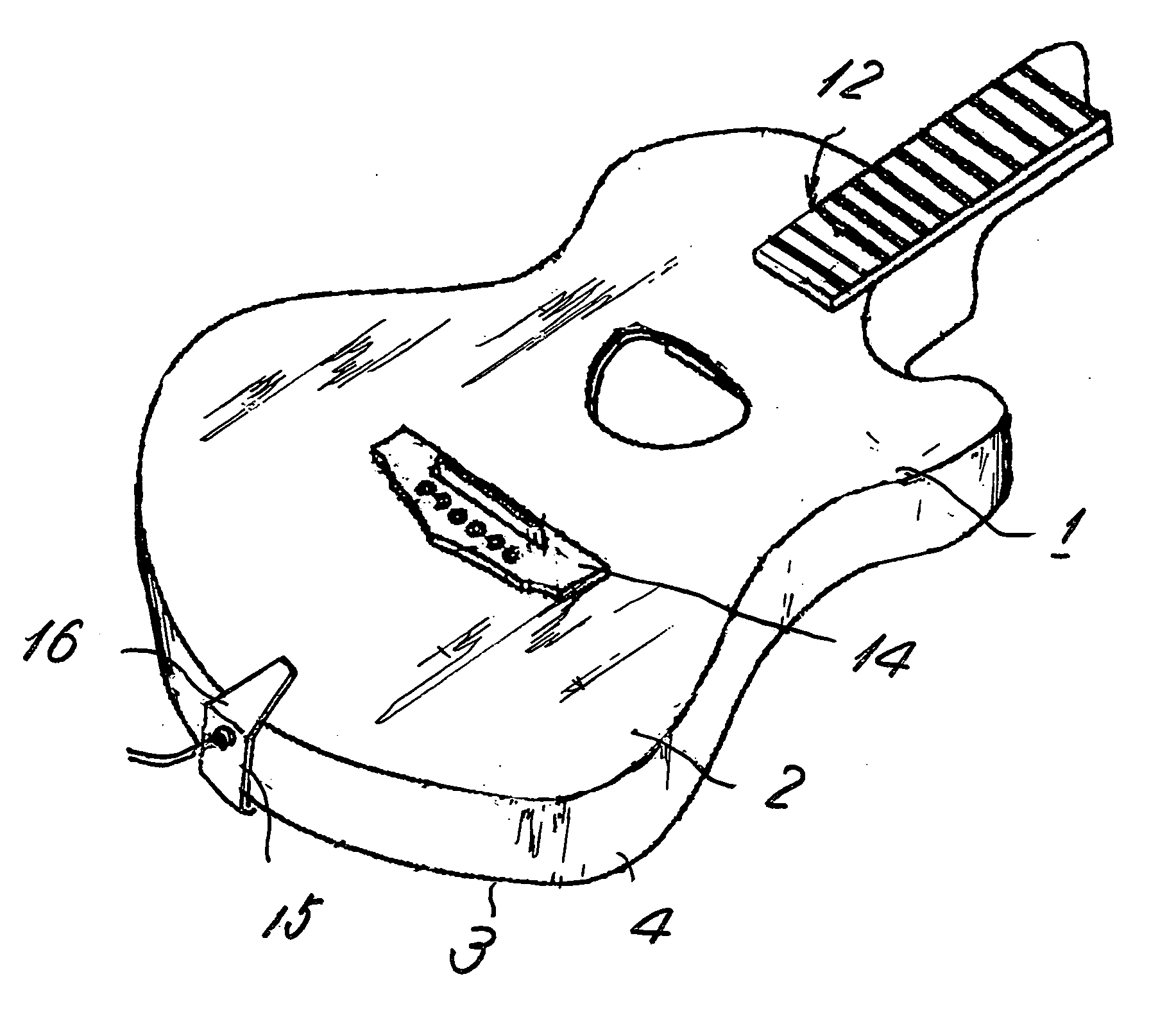
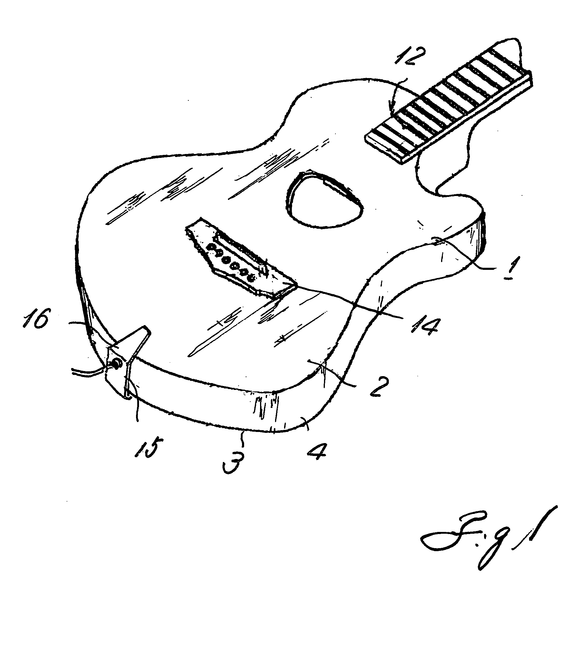
[0097] A vibration sensor mechanism (15) according to the present invention operates as described below. By way of example, the vibration sensor mechanism (15) is composed of a hook-like sensor mounting member (16) one side of which is folded downward and which has a screw hole (20) formed in the folded portion (17) so as to extend upward, a hook-like holding member (19) one side of which is folded upward and which has a through hole (21) formed in the folded portion (18), and an adjusting screw (23) inserted upward through the through hole (21) so as to screw a thread (22) formed in the upper part of the screw, into the upper screw hole (20).

[0098] The vibration sensor mechanism (15) is U-shaped (shaped like a horse shoe) so that its tip appears to be open (24) in a side view and that the open (24) portion can be pushed and set over a tail portion of the stringed instrument main body (1).

[0099] An angle adjusting mechanism in the sensor mechanism (15) is simpler tha...

embodiment 2

[Embodiment 2]

[0108] In the above embodiment, the vibration transmitter (30) is sandwiched between the blastomeric intermediate member (27) and the vibration plate (2). In this case, when the sensor mechanism (15) is mounted on the resonant housing portion (11) or removed from it, the vibration transmitter (30) may slip out to make the mounting difficult or may be lost.

[0109] Thus, as shown in FIG. 5, the intermediate member (27) may be made of a magnetic material, and a permanent magnet (31) may be embedded in the vibration transmitter (30). This prevents the vibration transmitter (30) from slipping easily off the intermediate member (27) and allows their angles to be smoothly adjusted.

embodiment 3

[Embodiment 3]

[0110] Furthermore, in the above embodiment, the sensor member (25) is mounted on the sensor mounting member (16) of the sensor mechanism (15). However, the sensor member (25) has been found to be similarly effective even when it is mounted on the vibration plate (2) of the device main body (1) as shown in FIG. 6.


PUM


Abstract

It is an object of the present invention to provide a pickup device for a stringed instrument which can take a piezoelectric signal for a tone of an acoustic stringed instrument. A stringed instrument is composed of a stringed instrument main body and a sensor mechanism. The stringed instrument main body is composed of one or more strings, a vibration plate used to radiate the vibration of each string as a sound wave, and a sensor mechanism that can make pressure contact with the vibration plate of the stringed instrument main body. The sensor mechanism has fixing means configured to be secured to the stringed instrument main body and a contact sensor member tightly contacted with the vibration plate directly or via an intermediate member.

Description

BACKGROUND OF THE INVENTION [0001] 1. Field of the Invention [0002] The present invention relates to a pickup device for an acoustic stringed instrument typified by a guitar, a ukulele, a mandolin, a violin, a cello, a contrabass, a banjo, or a samisen, and more specifically, to a sound processing method and a pickup device vibration sensor for a stringed instrument which convert the vibration force of the stringed instrument into electric signals for output. [0003] 2. Description of the Related Art [0004] Naturally, in particular, stringed instruments require an excellent pickup device which allows strings to exhibit well-balanced acoustic characteristics, which can provide favorable outputs, and which does not hinder the propagation of the vibration of the strings to the body, which is characteristic of acoustic stringed instruments. [0005] For this purpose, to collect electrically sounds from an acoustic stringed instrument, a microphone attached to a stand was frequently used. H...

Claims


Application Information

Patent Timeline
IPC IPC(8): G10H1/32G10H3/14
CPCG10H1/32G10H2220/525G10H3/146
Inventor KIYOHIKO, YAMAYA
Owner KIYOHIKO YAMAYA
Why Eureka
Try Eureka