Coin drop mechanism

a coin mechanism and coin drop technology, applied in the field of coin mechanisms, can solve the problems of complex arrangement, machine subject to weather extremes and abuse, complex coin mechanism, etc., and achieve the effect of minimizing discomfort or pain

Active Publication Date: 2008-12-30
BOBRICK WASHROOM EQUIP +1
View PDF16 Cites 13 Cited by
  • Summary
  • Abstract
  • Description
  • Claims
  • Application Information

AI Technical Summary

Benefits of technology

[0008]A user can actuate the coin mechanism to dispense a product by actuating an actuator. The actuator causes an actuation member to travel through the actuator opening in one member, engage a coin against the surface of the channel member, and displace the channel member relative to the support member. The channel member is connected to a product delivery system, which is configured to deliver a desired product upon displacement of the channel member.
[0009]The coin mechanism advantageously does not require complex electronic or mechanical parts. Additionally, the mechanism advantageously does not require the turning of a knob or rotation of a lever, minimizing the discomfort or pain suffered by individuals with limited hand movement during actuation of the mechanism.
[0010]Further, the contoured shape of the of the coin mechanism channel advantageously prevents fraudulent attempts to obtain a selected product by inserting, for example, an elongated flat object into the coin slot instead of the at least one coin.

Problems solved by technology

Such vending machines are located in a variety of locations, often making the machines subject to weather extremes and abuse, such as fraudulent attempts to obtain product without inserting the required purchase price.
Some conventional coin mechanisms are complex and utilize electronic parts to actuate the coin mechanism.
Other conventional coin mechanism designs are mechanically operated but employ a complex arrangement.
Although such mechanisms may be versatile and perform well under ideal conditions, they are inherently expensive and prone to requiring frequent maintenance due to the harsh conditions under which vending machines sometimes operate.
Such modes of actuation are difficult and sometimes painful for individuals with limited hand movement, such as individuals who suffer from arthritis or similar debilitating conditions.

Method used


Image

  • Coin drop mechanism
  • Coin drop mechanism
  • Coin drop mechanism

Examples


Embodiment Construction

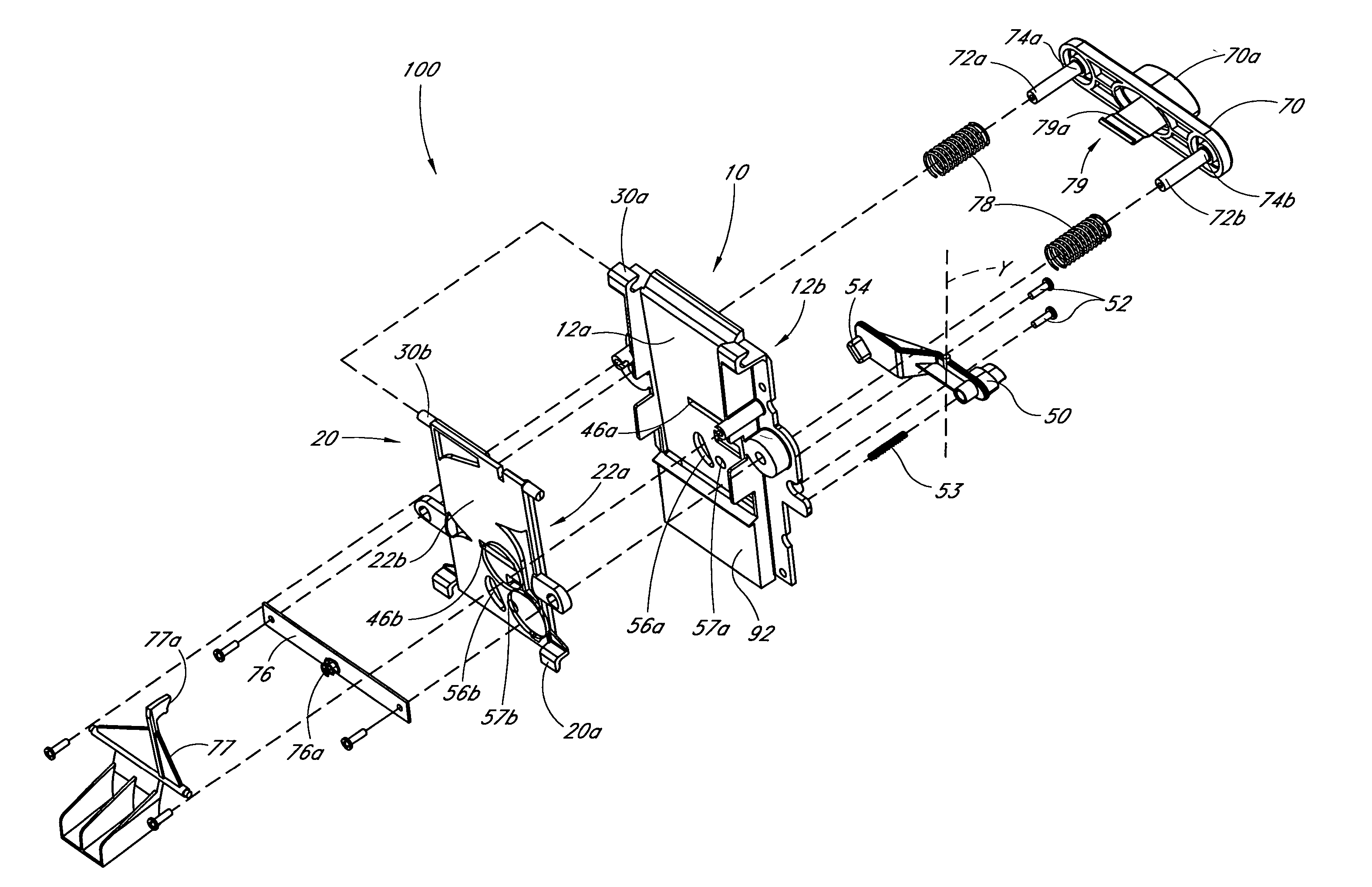
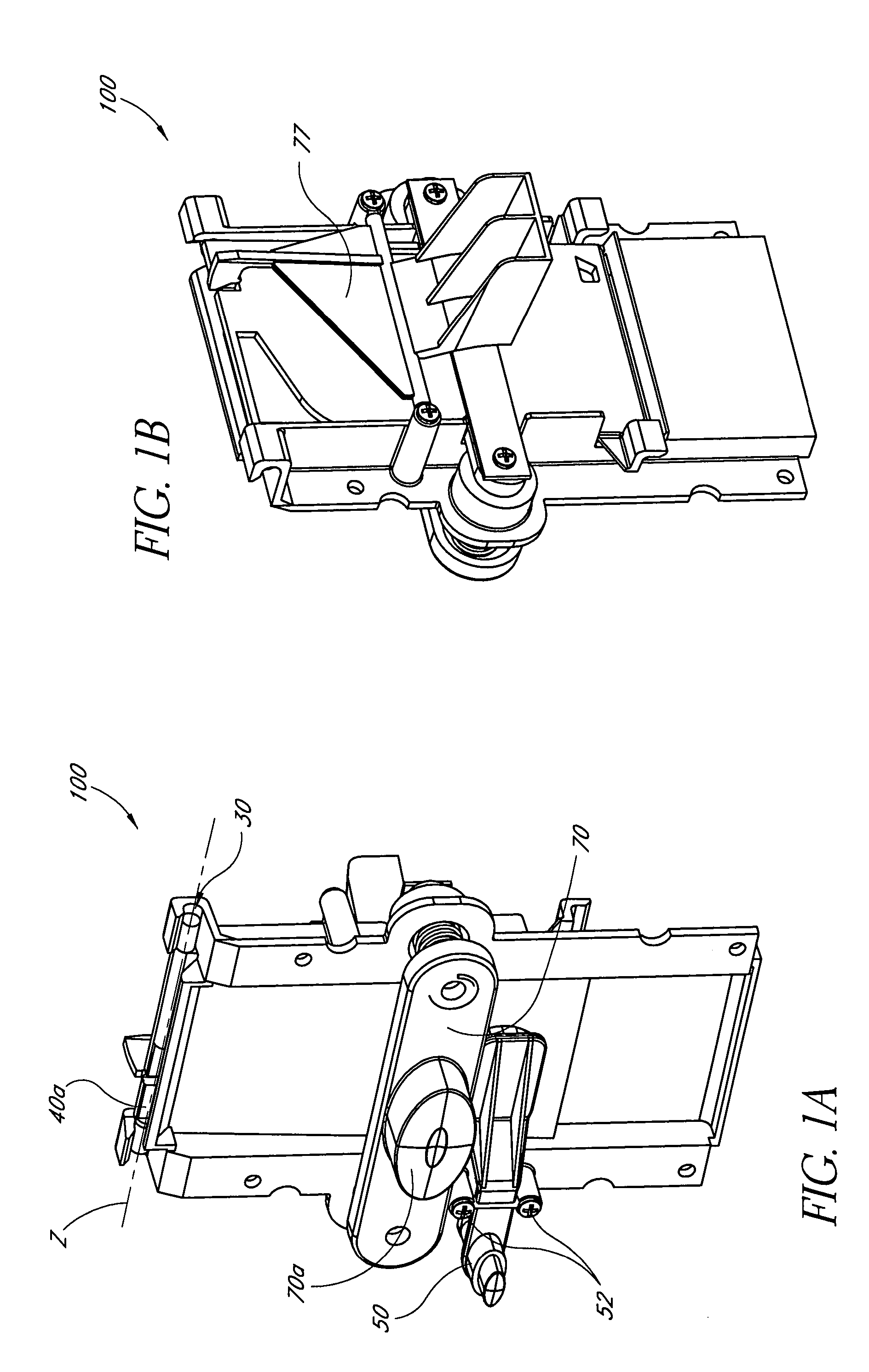
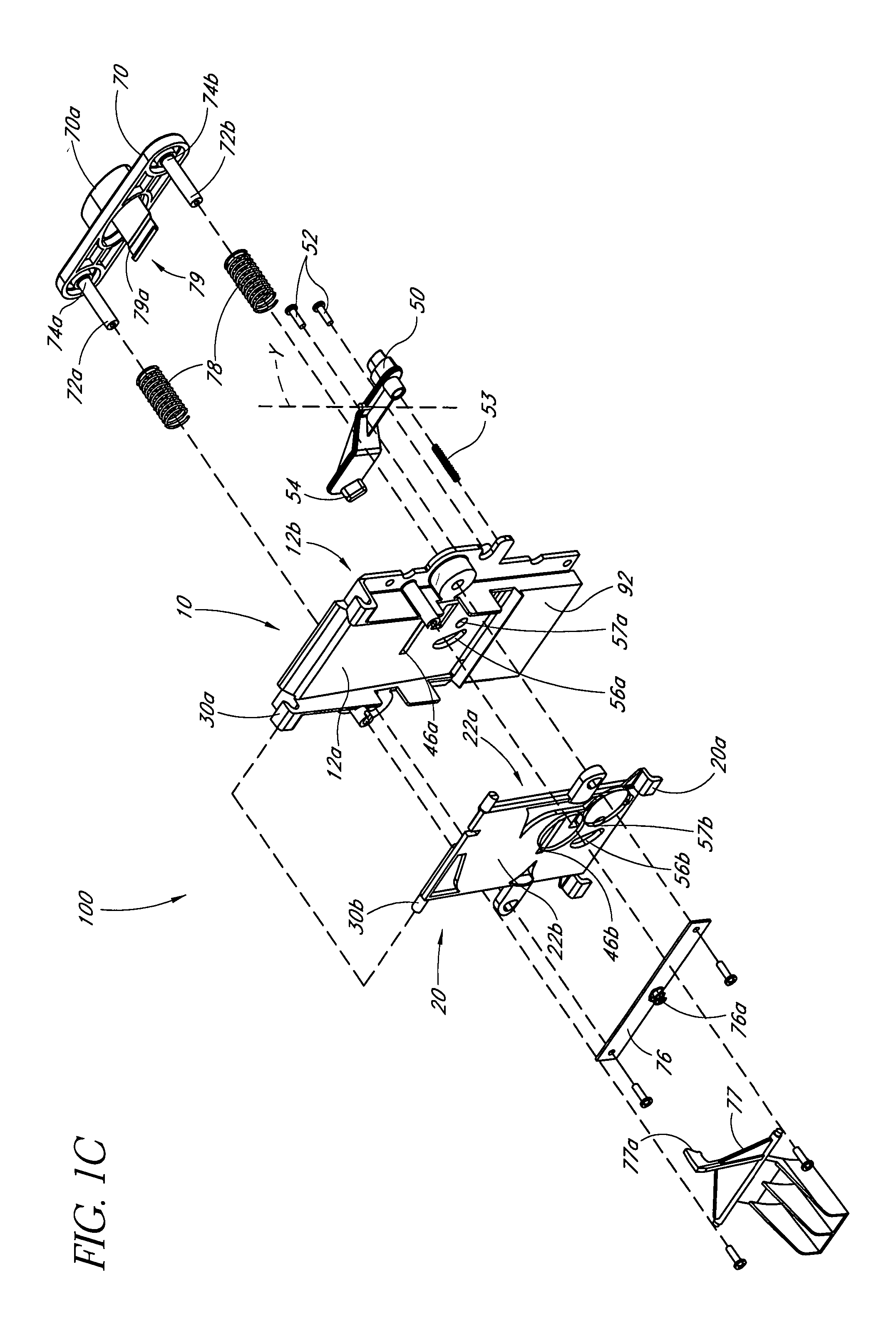
[0024]FIGS. 1a-1f illustrate a coin mechanism 100 according to one embodiment of the present invention. The mechanism 100 preferably comprises a support member 10 and a channel member 20. The members 10, 20 are shown as plates 10, 20 in the illustrated embodiment. However, the members 10, 20 are not limited to any geometrical shape. The members 10, 20 comprise inner surfaces 12a, 22a and outer surfaces 12b, 22b, respectively.

[0025]The members 10, 20 are preferably made of metal, such as steel or aluminum. However, the members 10, 20 can be made of any material having structural characteristics suitable for use in a coin mechanism 100, such as a hard plastic. Additionally, the members 10, 20 are preferably connected together so as to allow movement of the members 10, 20 relative to each other about an axis “Z”. For example, the support member 10 can have a female portion 30a, such as a hook, and the channel member 20 can have a male portion 30b configured to fit in the female portion...


PUM


Abstract

A coin drop mechanism comprises a support member movably connected to a channel member. A contoured channel configured to receive at least one coin is formed on at least one of the members and defines a coin slot when the members are in contact with each other. The channel is configured to guide the at least one coin to a desired location aligned with an actuator opening on the members. The mechanism further comprises an actuator. The actuator comprises a actuation member configured to travel through the actuator opening, engage the at least one coin against a surface of the channel member, and displace the channel member relative to the support member causing a selected product to be dispensed from a product receptacle.

Description

BACKGROUND OF THE INVENTION[0001]1. Field of the Invention[0002]The present invention relates to vending machines and, more particularly, to a coin mechanism used to actuate vending machines.[0003]2. Description of the Related Art[0004]Vending machines and coin mechanisms for operating such machines are well known in the art. Such vending machines are located in a variety of locations, often making the machines subject to weather extremes and abuse, such as fraudulent attempts to obtain product without inserting the required purchase price. Accordingly the coin mechanism for such machines must be of a non-complex design capable of withstanding such abuse.[0005]Some conventional coin mechanisms are complex and utilize electronic parts to actuate the coin mechanism. Other conventional coin mechanism designs are mechanically operated but employ a complex arrangement. Although such mechanisms may be versatile and perform well under ideal conditions, they are inherently expensive and pro...

Claims


Application Information

Patent Timeline
Patent Type & Authority Patents(United States)
IPC IPC(8): G07F5/00G07F11/00G07F13/00G07F15/00G07F17/00G07F1/04
CPCG07F1/047
Inventor HORIAN, JAMES G.
Owner BOBRICK WASHROOM EQUIP
Why Eureka
Try Eureka