Termite presence monitor and method

a monitor and termite technology, applied in the field of termite presence monitor and method, can solve the problems of large cost reduction in the cost of core drill, other core drilling equipment, labor required, etc., and achieve the effect of reducing cost, enduring high pressure, and high pressur

Inactive Publication Date: 2009-01-13
MEDIATE DONALD L
View PDF12 Cites 7 Cited by
  • Summary
  • Abstract
  • Description
  • Claims
  • Application Information

AI Technical Summary

Benefits of technology

[0006]The method and termite-monitoring device of the subject invention accomplish all of the goals listed above. In particular, with respect to the detection and extermination of termites beneath a pavement, the termite-monitoring device of the subject invention only requires the boring of holes through the pavement that are typically about one inch or less in diameter and, preferably, are only about three-quarters of an inch in diameter. This results in a large cost reduction in the core drills, other core drilling equipment, and labor required to form the paving holes in the pavement for the termite-monitoring devices. In addition, with its convex, low profile upper surface design, the closure component of the termite-monitoring device of the subject invention can withstand up to 1500 psi (pounds per square inch) without fracturing and is not susceptible to being caught up by street or pavement cleaning equipment or apparatus so that, in service, the termite-monitoring device is not susceptible to being pulled from a paving hole, damaged, or broken apart by street or pavement cleaning equipment or apparatus. The ability of the closure component of the termite-monitoring device of the subject invention to withstand high levels of pressure without fracturing is important in that the closure components of the termite-monitoring devices of the subject invention can be subjected to high levels of pressure in service, such as but not limited to that produced when the closure components are stepped on by persons wearing shoes with stiletto heels.

Problems solved by technology

This results in a large cost reduction in the core drills, other core drilling equipment, and labor required to form the paving holes in the pavement for the termite-monitoring devices.

Method used


Image

  • Termite presence monitor and method
  • Termite presence monitor and method
  • Termite presence monitor and method

Examples


Embodiment Construction

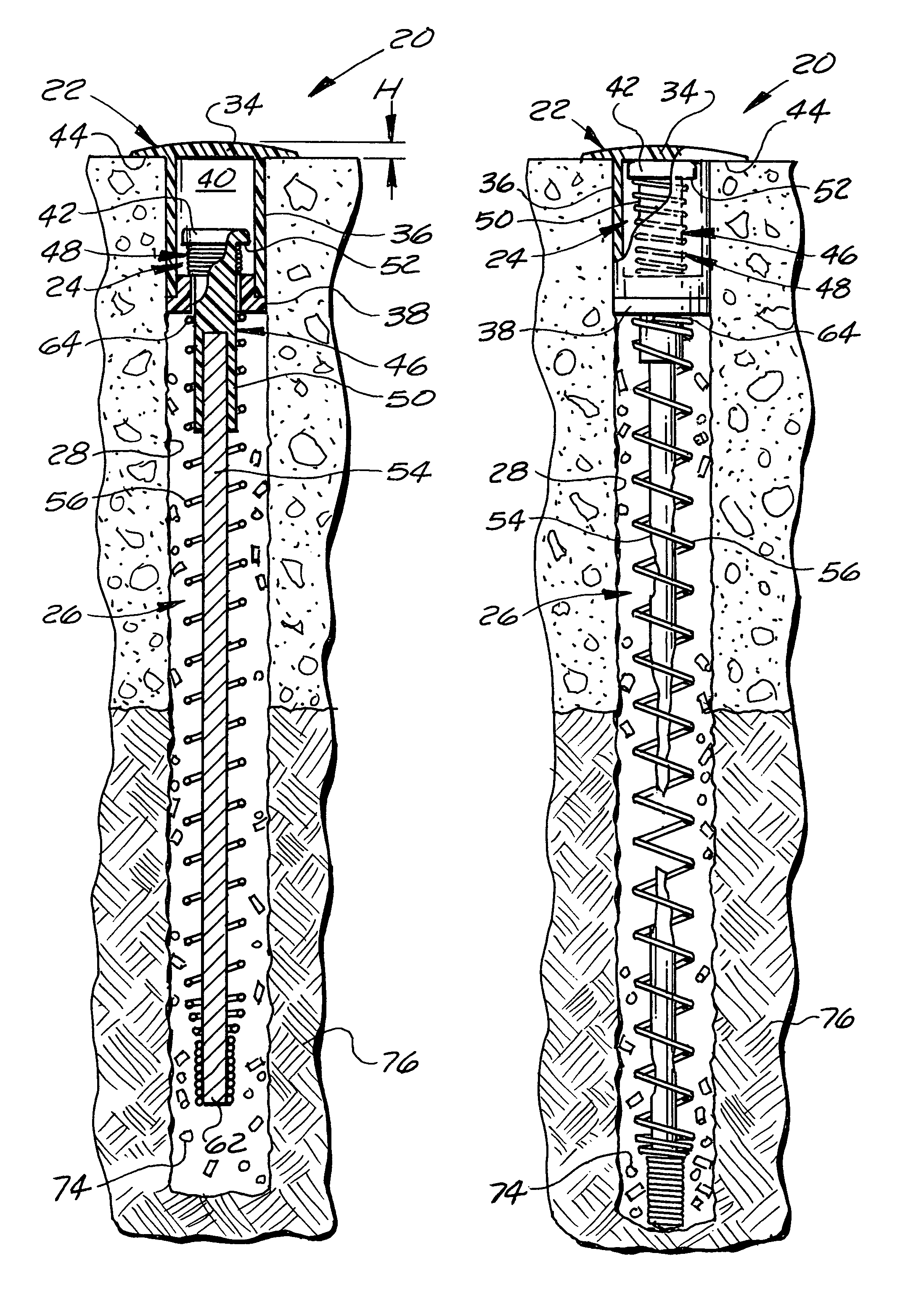
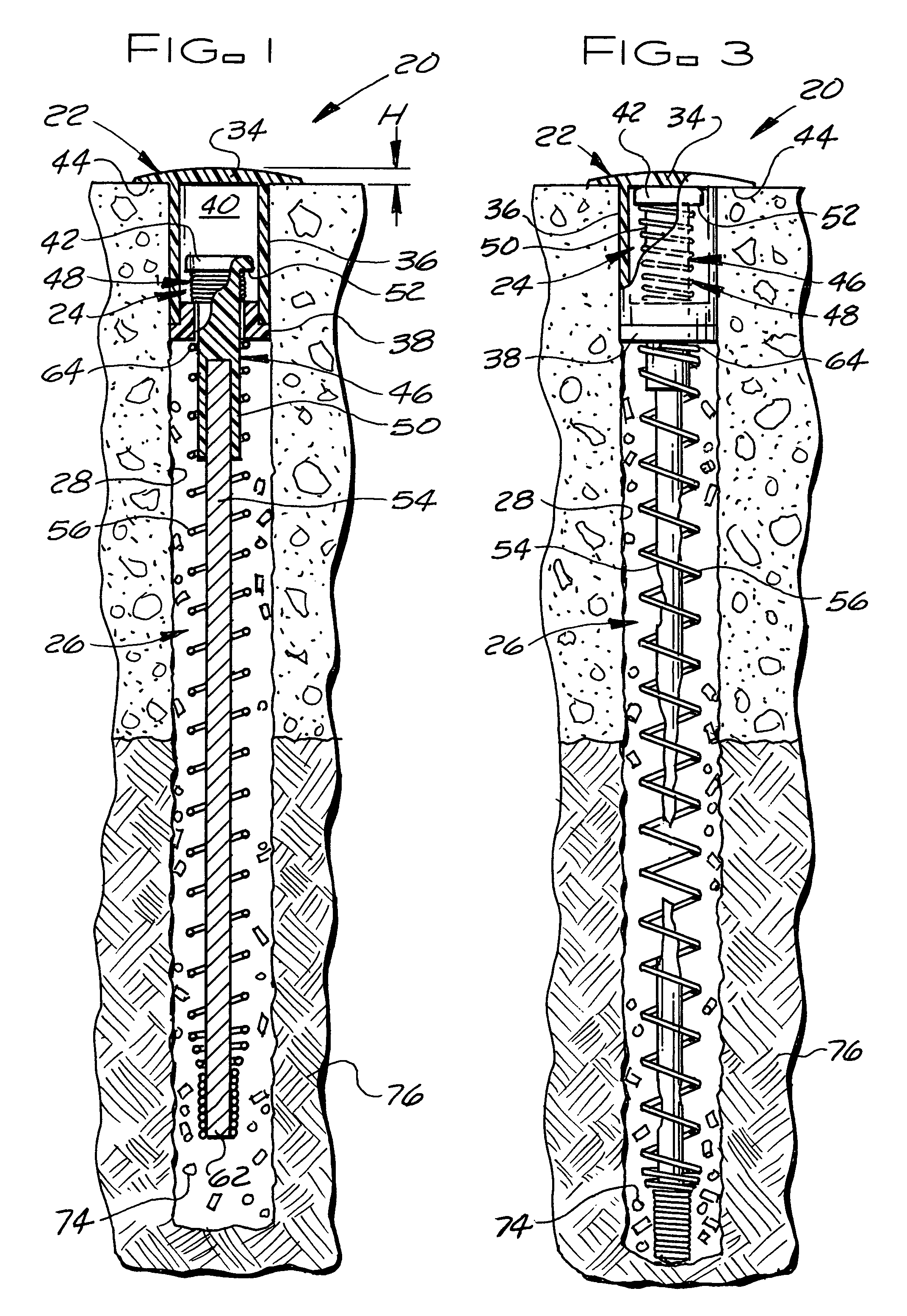
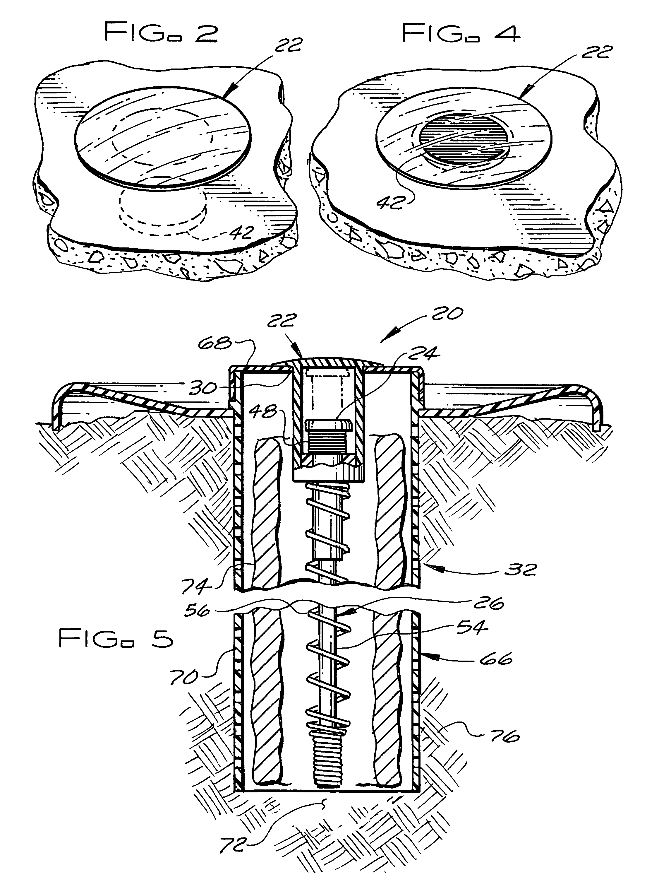
[0021]As shown in FIGS. 1 to 5, a first embodiment 20 of the termite-monitoring device of the subject invention for use in the method of the subject invention includes a closure component 22, a termite presence indicator mechanism 24, and a trigger mechanism 26. The closure component 22 houses the termite presence indicator mechanism 24. In addition, when the termite-monitoring device 20 is mounted in a paving hole 28 or in a hole 30 of a termite lure 32 extending down into the termite lure from the upper surface of the termite lure, as shown in FIG. 5, the closure component 22 closes the upper end of the paving hole 28 or the termite lure hole 30 and seals the interior of the hole from the elements. The closure component 22 includes an upper end portion 34, a tubular housing portion 36 extending downward from the upper end portion, and a lower end portion 38 formed by a plug. The upper end portion 34 of the closure component 22 closes an upper end and the lower end portion 38 of th...


PUM


Abstract

A termite-monitoring device and method for detecting the presence of termites and killing termites by exposing the termites to a termiticide, includes locating the monitoring device in a paving hole or in a termite lure located in the ground adjacent a building. The monitoring device has an integral termite indicator mechanism for indicating the presence of termites within the paving hole or termite lure that provides an aboveground visible indicator that termites are present. The termite indicator mechanism is actuated by a trigger mechanism with a termite food source that, when fed upon by termites, actuates the termite indicator mechanism to indicate the presence of termites. After the indicator has been actuated, a termiticide is introduced into the paving hole, the termite lure, and / or the adjacent ground to expose termites to the termiticide as the termites pass between a termite colony and the paving hole or termite lure and / or feed within the paving hole or termite lure.

Description

[0001]This patent application is a continuation-in-part application of patent application Ser. No. 11 / 370,330, filed Mar. 8, 2006, now abandoned.BACKGROUND OF THE INVENTION[0002]The subject invention relates to method for monitoring for the presence of termites and exterminating termites once their presence is detected and to a termite-monitoring device that, while it can be used with in-ground termite lures, is especially adapted for use in the detection of termites beneath pavements (e.g. concrete and asphalt pavements such as but not limited to slabs, walkways, and roads).[0003]Termites do more property damage in the United States than hurricanes, earthquakes and vandalism combined. In order to control termites with a toxicant (hereinafter “termiticide”), termites must come in contact with the termiticide. Termites ingress and egress a food source through underground and above ground tunnel tubes which extend between a colony nest and the food source, e.g. a building. These tunne...

Claims


Application Information

Patent Timeline
Patent Type & Authority Patents(United States)
IPC IPC(8): A01M1/20
CPCA01M1/026
Inventor MEDIATE, DONALD L.
Owner MEDIATE DONALD L
Why Eureka
Try Eureka