Wing employing leading edge flaps and winglets to achieve improved aerodynamic performance

a leading edge flap and aerodynamic technology, which is applied in the direction of canard-type aircraft, air-flow influencers, transportation and packaging, etc., can solve the problem of lower induced drag at the cruise mach number, achieve the effect of reducing trim and vortex drag, reducing the sonic boom signature of the supersonic aircraft, and increasing aft li

Active Publication Date: 2009-01-13
SUPERSONIC AEROSPACE INT
View PDF33 Cites 49 Cited by
  • Summary
  • Abstract
  • Description
  • Claims
  • Application Information

AI Technical Summary

Benefits of technology

[0007]What are desired are wings and lift devices that facilitate sonic boom reduction and enable good off-design performance and control characteristics.
[0008]Some embodiments disclosed herein teach a wing for use on a supersonic aircraft that includes an inboard section a central section of the wing outboard of the inboard portion, and an outboard section. The outboard section can be a winglet oriented anhedrally relative to a lateral axis of the supersonic aircraft. Leading edge segments on the inboard section, central section and outboard winglet may have mounted thereon leading-edge flaps. These flaps are adjusted by a control system operable to reposition the leading-edge flaps in order to improve the aerodynamic performance of the supersonic aircraft. This winglet promotes sonic boom minimization. Further, the wing tip anhedral allows greater inboard dihedral. This effectively pushes lift aft for sonic boom and control purposes while minimizing the movement of control surfaces.
[0009]In further embodiments, the outboard lower sweep section has the same dihedral angle as the inboard portions of the wing. This embodiment shifts the aircraft's aerodynamic center and center of pressure aft. This shift aft helps achieve a minimized sonic boom according to the methodology of George-Seebass-Darden and prior patent U.S. patent application Ser. No. 10 / 006,505, entitled Tail-Braced Wing Aircraft and Configurations for Achieving Long Supersonic Range and Low Sonic Boom, which is hereby incorporated by reference. It also results in lower induced drag at the cruise Mach number because the outboard section can trap all the upwash generated by the inboard wing, behind the Mach cone angle but ahead of the inboard wing leading edge. This makes the outboard wing a more efficient place to generate lift than otherwise possible. Integrating this outboard with sonic boom minimization, by keeping the equivalent area less than or equal to the George-Seebass-Darden ideal equivalent area definition, allows the aft load needed for minimization to be met with less induced drag. The tip of the outboard wing may have a leading edge flap or all-moving tip for roll control with less aeroelastic effectiveness loss due to twist, especially supersonically.

Problems solved by technology

It also results in lower induced drag at the cruise Mach number because the outboard section can trap all the upwash generated by the inboard wing, behind the Mach cone angle but ahead of the inboard wing leading edge.

Method used


Image

  • Wing employing leading edge flaps and winglets to achieve improved aerodynamic performance
  • Wing employing leading edge flaps and winglets to achieve improved aerodynamic performance
  • Wing employing leading edge flaps and winglets to achieve improved aerodynamic performance

Examples


Embodiment Construction

[0035]Preferred embodiments of the present invention are illustrated in the FIGURES, like numerals being used to refer to like and corresponding parts of the various drawings.

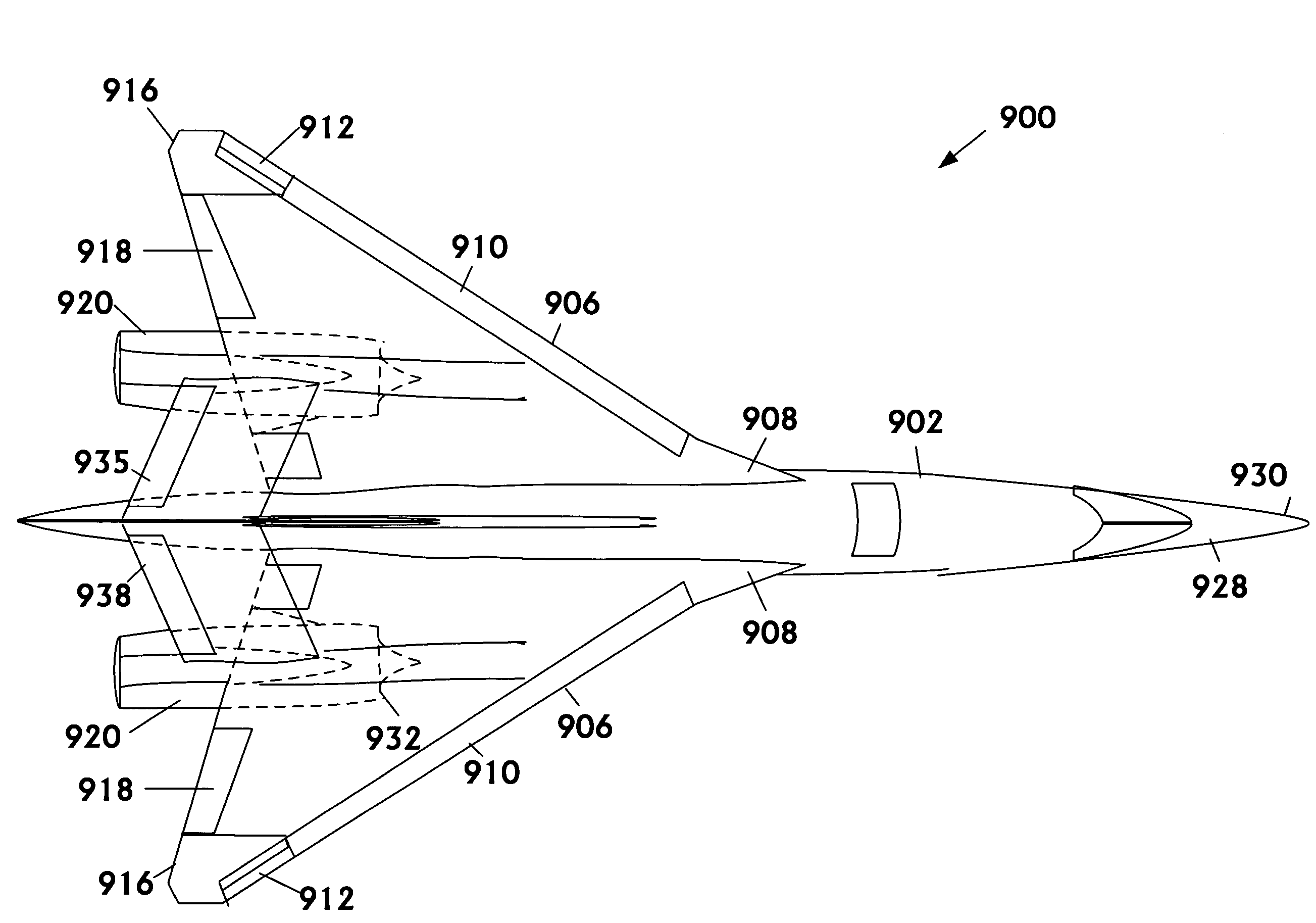
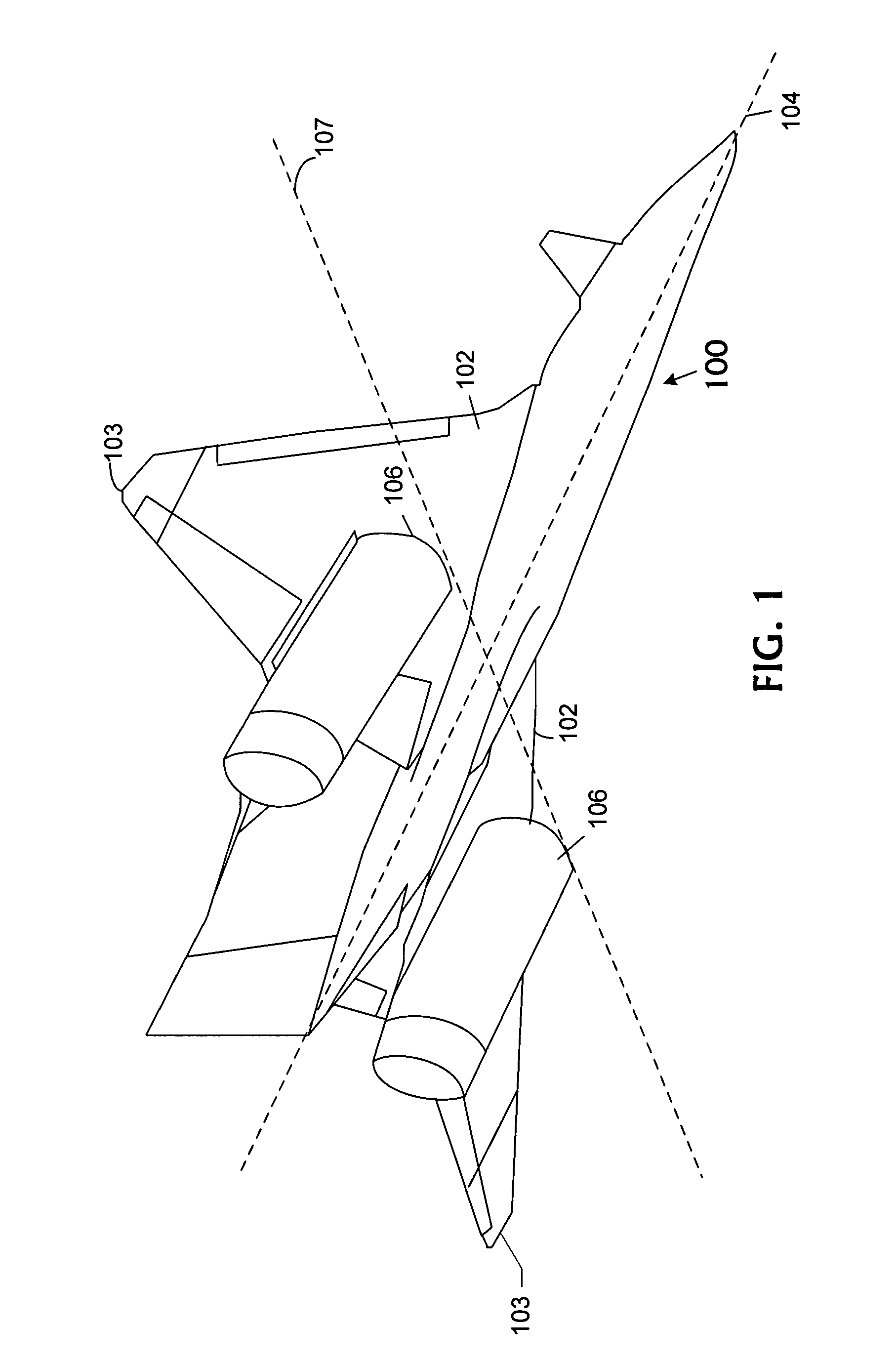
[0036]FIG. 1 illustrates an example of an aircraft 100 having a longitudinal axis 104 forward and aft to which an airfoil is coupled. Airfoils are generally designed to maximize aerodynamic performance at a particular Mach number or range of Mach numbers. In various circumstances and conditions, operation at off-design Mach numbers is desirable. The airfoil includes aircraft wings 102. However, the airfoil may also include other aerodynamic shapes including the fuselage, tail, and other structures within the air stream. Wings 102 can further include winglets 103.

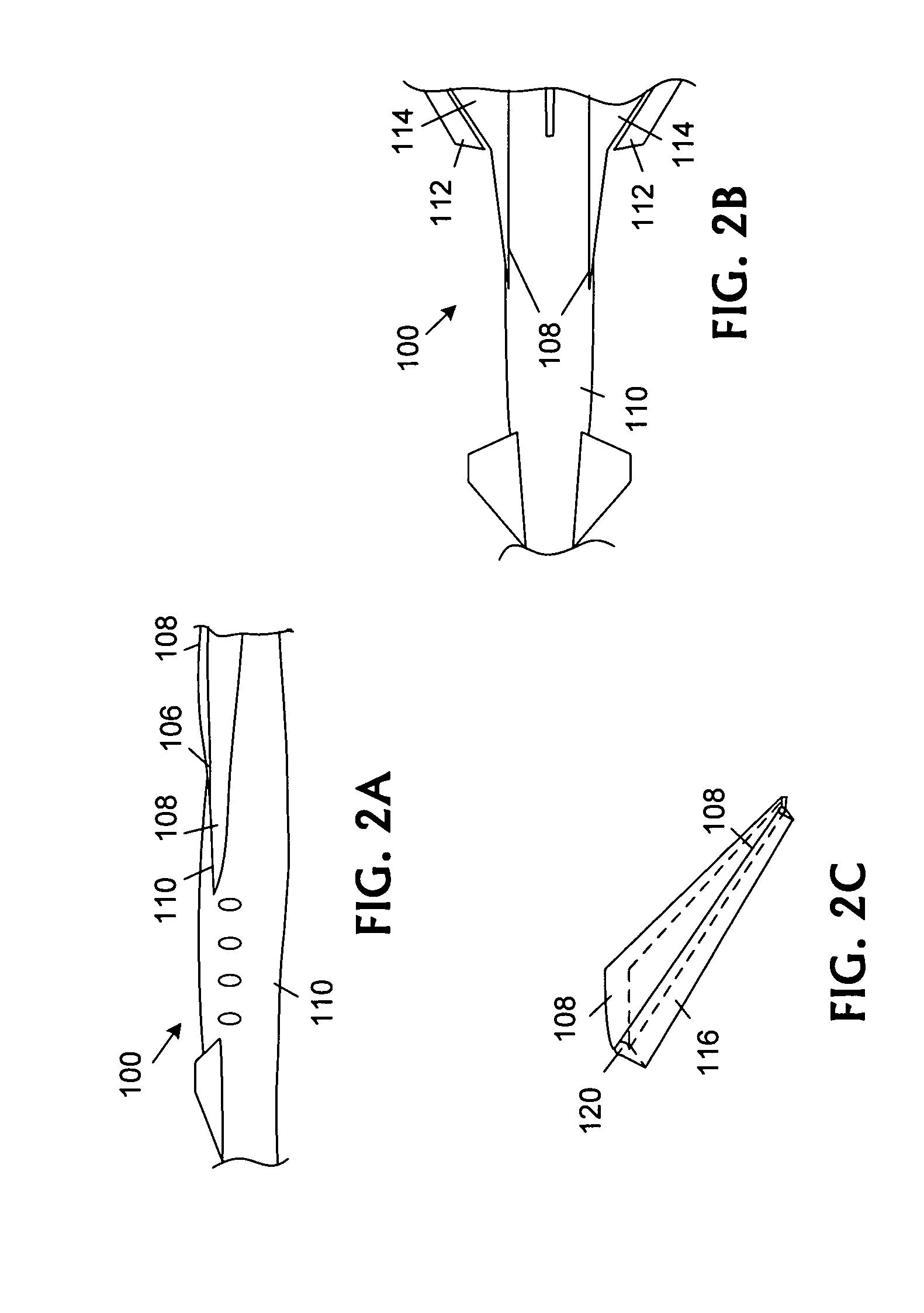
[0037]FIGS. 2A, 2B, and 2C illustrate side, top, and three-dimensional perspective views of an embodiment of portions of wings for usage on aircraft 100. Wings 102 couple to a strake 108 that couples to aircraft fuselage 110 and extends along a portion ...


PUM


Abstract

A wing for use on a supersonic aircraft that includes an inboard section a central section of the wing outboard of the inboard portion, and an outboard section. The outboard section can be a winglet oriented anhedrally relative to a lateral axis of the supersonic aircraft. Leading edge segments on the inboard section, central section and outboard winglet may have mounted thereon leading-edge flaps. These flaps are adjusted by a control system operable to reposition the leading-edge flaps in order to improve the aerodynamic performance of the supersonic aircraft. This winglet promotes sonic boom minimization. Further, the wing tip anhedral allows greater inboard dihedral. This effectively pushes lift aft for sonic boom and control purposes while minimizing the movement of control surfaces.

Description

BACKGROUND OF THE INVENTION[0001]Air travelers have long sought the convenience and efficiency of widespread supersonic commercial aviation only to be denied by technological, economic, and political roadblocks. With operations spanning over a quarter of a century, the Concorde remains the only commercial aircraft that travels at supersonic speeds but struggles with technological obsolescence. Fuel consumption and maintenance requirements of the Concorde strain commercial feasibility in today's competitive environment. Possibly overshadowing other technological and economic shortcomings is the Concorde's thunderous sonic boom that is highly annoying due to its perceived loudness and startle, a burden that restricts the Concorde's supersonic operations to primarily oceanic routes.[0002]The sonic boom imposes many practical limitations for commercial supersonic aviation as annoyance with sonic boom loudness and startle results in the prohibition of commercial supersonic aircraft opera...

Claims


Application Information

Patent Timeline
Patent Type & Authority Patents(United States)
IPC IPC(8): B64C3/00B64C3/16B64C5/02B64C5/04B64C5/12B64C7/00B64C9/22B64C9/32B64C9/36B64C13/50B64C23/04B64C30/00B64C39/12
CPCB64C3/16B64C5/02B64C5/04B64C5/12B64C7/00B64C9/22B64C9/32B64C9/323B64C9/36B64C23/04B64C30/00B64C39/12Y02T50/12Y02T50/32Y02T50/44Y02T50/10Y02T50/30Y02T50/40
Inventor MORGENSTERN, JOHN M.ARSLAN, ALAN E.
Owner SUPERSONIC AEROSPACE INT
Why Eureka
Try Eureka