Illumination of vehicle instrument

a vehicle instrument and illumination technology, applied in the direction of instruments, measurement device, measurement apparatus components, etc., can solve the problems of reducing the aesthetic appeal of the instrument, requiring more complex arrangement of the pointer, and reducing the cost savings of such simplified designs, so as to achieve small area, improve aesthetics, and improve the effect of illumination

Inactive Publication Date: 2009-01-13
VISTEON GLOBAL TECH INC
View PDF4 Cites 15 Cited by
  • Summary
  • Abstract
  • Description
  • Claims
  • Application Information

AI Technical Summary

Benefits of technology

[0013]As seen from above, the invention achieves both front lighting and back lighting of the instrument from light sources mounted behind the dial. The benefits of front lighting as discussed above are therefore achieved without the need for mounting the light sources in front of the dial. The combination of back lighting and front lighting in a single instrument results in a pleasant aesthetic.
[0014]The first and second light sources are both located directly behind the pointer assembly and are preferably substantially centrally located behind the dial. In this position, the light sources are close to the other electronics, such as the pointer motor, which allows a smaller PCB to be used. Preferably the first and second light deflecting means are located proximate to the first axis, and most preferably the pointer assembly comprises the first and second light deflecting means. This arrangement means that the illumination system is very compact as all the lighting components are associated with the pointer assembly, and are hence substantially centrally located on the dial and occupy a relatively small area.
[0015]The centrally located first and second light sources produce a pleasant illumination pattern on the dial. The illumination pattern is bright at the center of the dial and gets evenly dimmer towards the outer periphery of the dial. By using separate first and second light sources to illuminate the pointer and the dial, respectively, a number of interesting effects can be achieved. The pointer is illuminated completely independently from the dial and so, for example, the pointer and dial could be illuminated by different colored light. Furthermore, the first and second light sources could have different brightnesses so that the contrast between the dial and the pointer can be varied. Separate dimmer functions may be associated with the first and second light sources to allow the contrast between pointer and dial to be continuously varied.
[0016]Preferably the first and second light sources emit light from substantially concentric annular regions centered about the first axis. The first light source preferably comprises a plurality of first light emitting diodes (LEDs) arranged in a first ring centered about the first axis, and the second light source preferably comprises a plurality of second LEDs arranged in a second ring centered about the first axis. The radius of the second ring is greater than the radius of the first ring such that the first LEDs form an inner ring, and the second LEDs form an outer ring. In most applications, the radius of the first ring is preferably between 2 and 5 mm, and more preferably about 3.5 mm. The radius of the second ring is preferably between 5 and 10 mm, and more preferably about 8.5 mm. The first and second LEDs are preferably each mounted directly to a PCB located behind the dial. Mounting the light sources directly on the PCB negates the requirement for flexible connectors or light guides and thus reduces cost.
[0023]The first and second light sources are located directly behind the pointer assembly, and all the lighting components are preferably located proximate to the first axis, and substantially behind the pointer hub. This allows a small PCB to be used. Preferably the pointer assembly includes a light absorbing cap located over the pointer hub which absorbs undeflected light from the first and second light sources, thus preventing the light from being transmitted towards a vehicle occupant. The light absorbing cap is preferably substantially circular and has a radius in excess of the radius of the outer ring of second LEDs to substantially obscure the area occupied by the first and second light sources from view, and hence obscures the lighting components from view. The light absorbing cap also protects the lighting components. Usually the instrument also includes a transparent front panel to protect the instrument and its components from dust, scratches and knocks.

Problems solved by technology

Front lighting can produce a more appealing effect than back lighting, however the lighting components in front lit instruments tend to be mounted in front of the instrument panel, and are therefore often visible to the vehicle occupant, which detracts from the aesthetic appeal of the instrument.
A problem with known front lit instruments is that while front lighting allows for a simpler design of the information bearing surface and the pointers, any cost savings that result from such simplified designs are negated by the extra costs required for flexible connectors from the PCB (which is located behind the instrument panel) to the light source or complex light guides (which are generally located in front of the instrument panel), and for more complex assembly.
Back lighting, on the other hand, usually involves the use of a plurality of light sources, and a more complex arrangement is required to illuminate the pointer.
Furthermore, applying symbols to the information bearing surface is more complex in the case of back lighting, because poor distribution of the illumination can cause portions of the instrument to have better illumination than others.

Method used


Image

  • Illumination of vehicle instrument
  • Illumination of vehicle instrument
  • Illumination of vehicle instrument

Examples


first embodiment

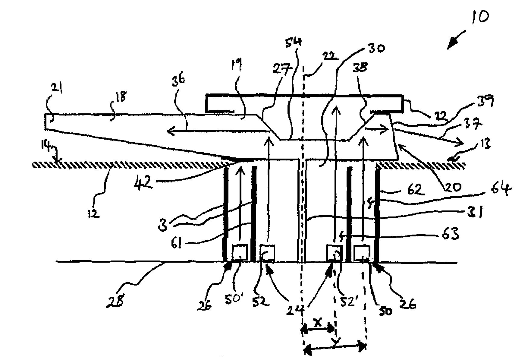
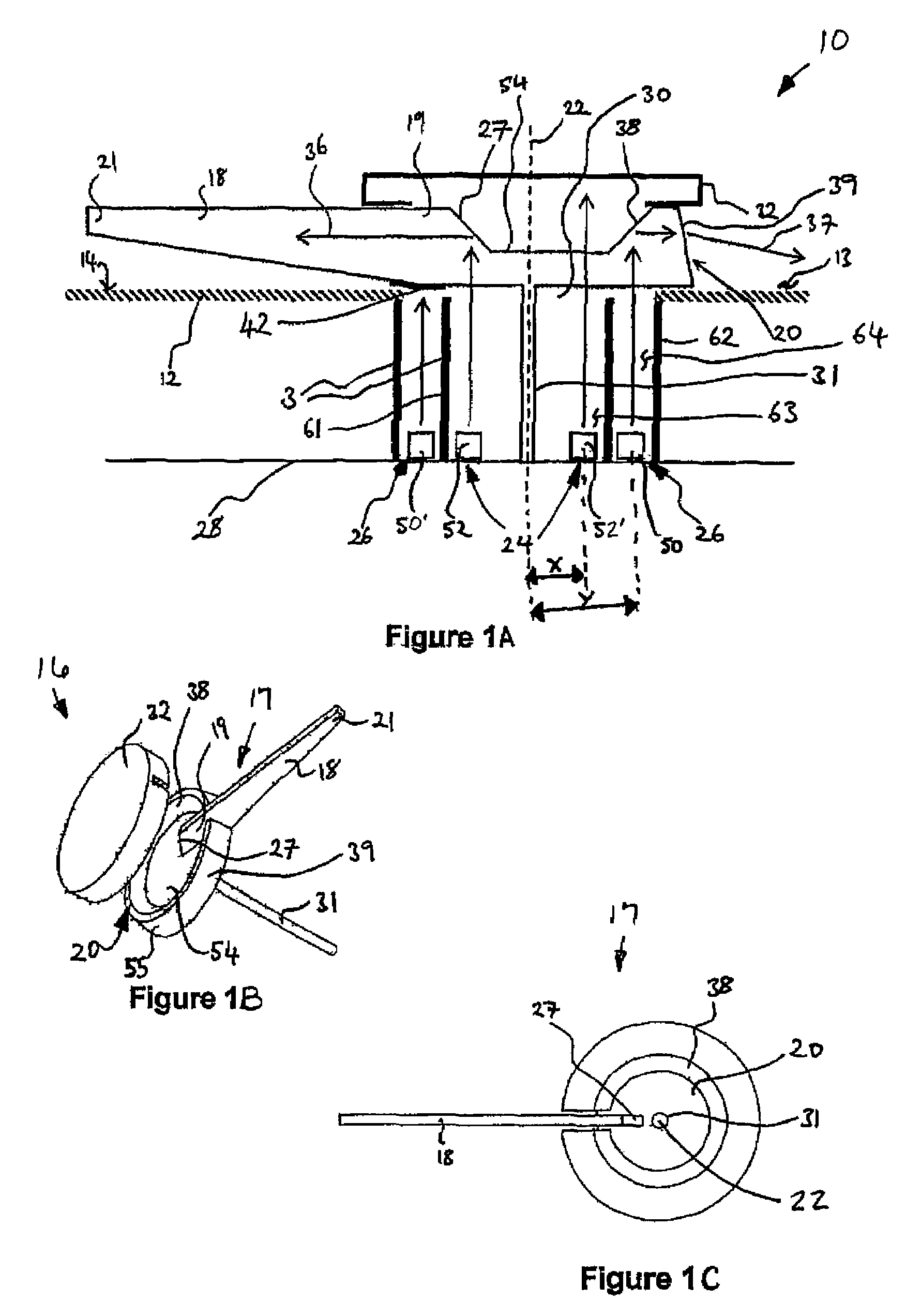
[0034]Referring now to FIG. 1A, seen therein is a diagrammatic cross-section through part of an instrument according to the present invention. The instrument 10 comprises a dial 12 having an information bearing front surface 14, which may include numbers and other marks (not shown). The instrument 10 also includes a pointer assembly 16 (shown in isolation in FIG. 1B) comprising a pointer 17 having a pointer hub 20 and a needle 18, a spindle 31 and a light absorbing cap 32. The pointer hub 20 is substantially circular, and the needle 18 extends radially from the hub 20. The needle 18 and hub 20 are mounted in front of the dial 12 on the viewing side 13 of the information bearing surface 14. The spindle 31 extends centrally from the underside of the hub 20 and extends perpendicular to the plane of the dial 12. The needle 18 is able to pivot or rotate about a first axis (indicated by the dotted line 22) which is perpendicular to the plane of the dial 22 and coincident or coaxial with t...

second embodiment

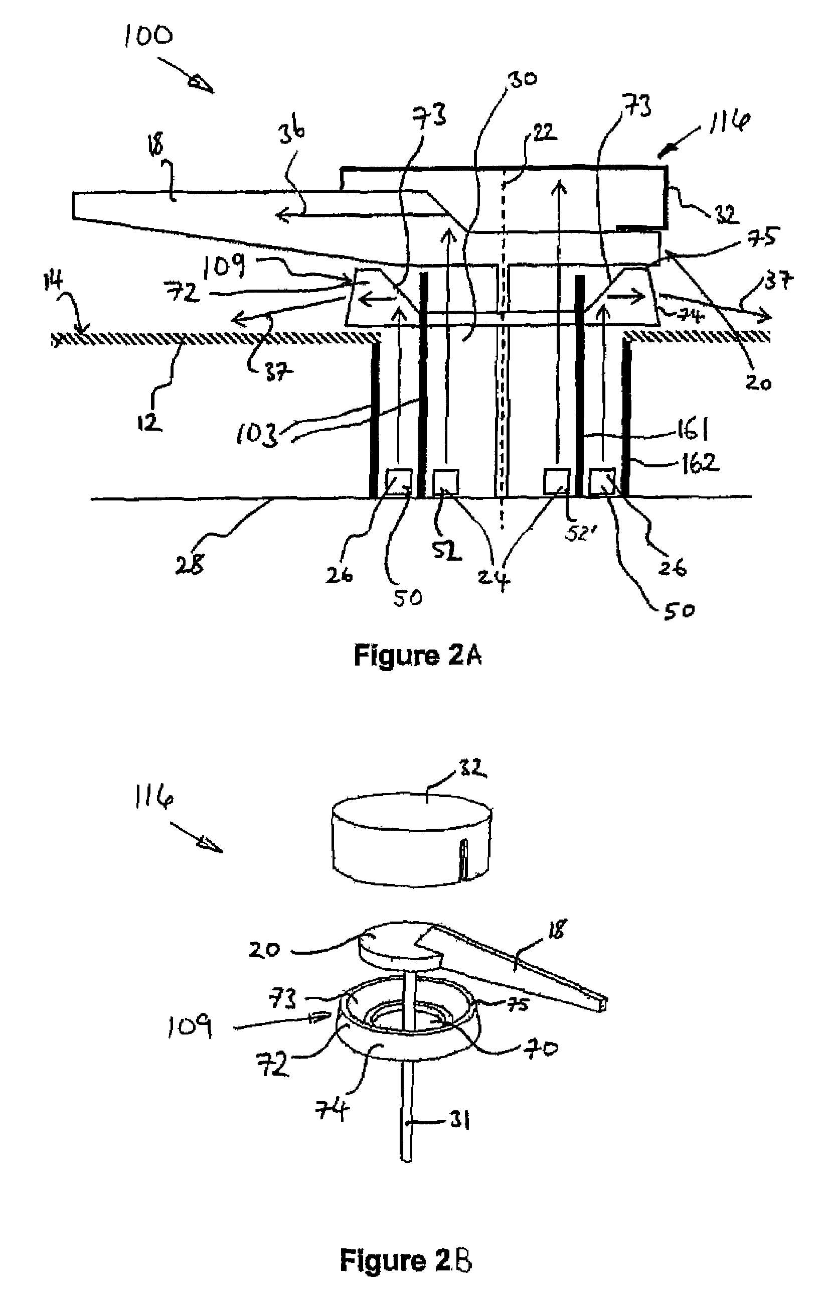
[0048]In this second embodiment, the deflection element 109 is generally located between the pointer 18 and the dial 12. The radius of the deflection element 109 is larger than the radius of the aperture 30 in the dial 12 to prevent the deflection element 9 from falling through the aperture 30. The light absorbing cap 32 is located over the pointer hub 20 obscure the light sources 24, 26 from view.

[0049]The light deflecting walls 103 in the second embodiment are arranged slightly differently to those in the first embodiment shown in FIG. 1. In the second embodiment, the first tube 161 is longer than the second tube 162, and extends through the aperture 30 in the dial 12 and through the central hole 70 in the deflecting element 9. The first tube 61 extends to a height substantially equal to the top 75 of the circumferential wall 72 of the deflection element 109, and the pointer hub 20 sits on top of the first tube 161 and deflection element 109.

[0050]The separate deflection element 1...


PUM


Abstract

An instrument suitable for use in a vehicle and having a dial with an information bearing front surface and a pointer for indicating information on the front surface. The pointer is pivotable about a first axis that extends through the hub and is substantially perpendicular to the plane of the dial. The instrument includes first and second light sources which are both located behind the dial, generally in registry with the pointer assembly. The instrument further includes a first light deflector that deflects light from the first light source along the pointer to back light the pointer, and second light deflector that deflects light from the second light source towards the front surface to front light that surface.

Description

BACKGROUNDField of the Invention[0001]The present invention relates to illumination of instruments, gages and dials, and particularly to instruments suitable for use in a vehicle.[0002]Instruments for displaying information on a vehicle display are usually located on the instrument panel of an automotive vehicle, and require some form of illumination to allow the driver to read the information when it is dark. An instrument usually comprises a panel or face having an information bearing region, and a housing having a transparent cover to protect the instrument. The information bearing region usually has symbols, such as graphics, numbers or a dial, indicating a scale and a pointer for indicating a point within the scale. The information bearing region may also include features such as rings defining the perimeter of a particular instrument, gauge or dial (hereafter “instrument”.[0003]The instrument is generally mounted on a printed circuit board (PCB) that is connected to sensors (d...

Claims


Application Information

Patent Timeline
Patent Type & Authority Patents(United States)
IPC IPC(8): G01D11/28
CPCG01D11/28G01D13/265B60K2370/6992B60Q3/10G01D13/02
Inventor MEZOUARI, SAMIR
Owner VISTEON GLOBAL TECH INC
Why Eureka
Try Eureka