Mobile device for heating rooms

Active Publication Date: 2010-01-07
DE LONGHI SPA
View PDF11 Cites 4 Cited by
  • Summary
  • Abstract
  • Description
  • Claims
  • Application Information

AI Technical Summary

Benefits of technology

[0034]In this way, the heat-insulating means protects from impacts against the radiant

Problems solved by technology

In the field of mobile heating devices of this type, one of the problems generally faced is that of transmitting heat energy in the room so as to heat the room as rapidly as possible, or to heat large-size rooms, keeping the temperature of the peripheral zones, which can easily come into contact with a part of the body of a user,

Method used


Image

  • Mobile device for heating rooms
  • Mobile device for heating rooms
  • Mobile device for heating rooms

Examples


Example

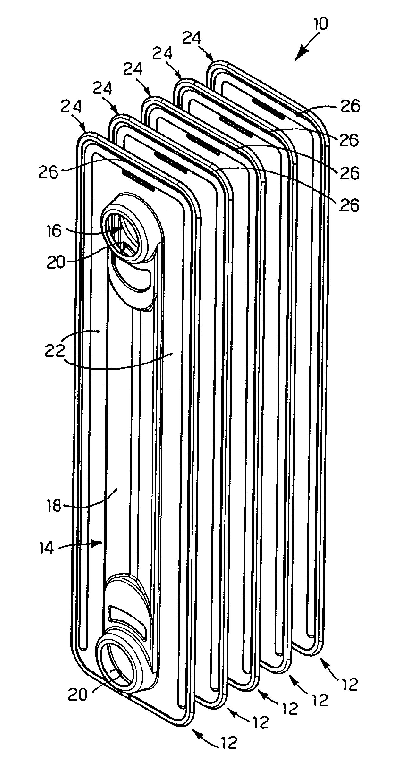
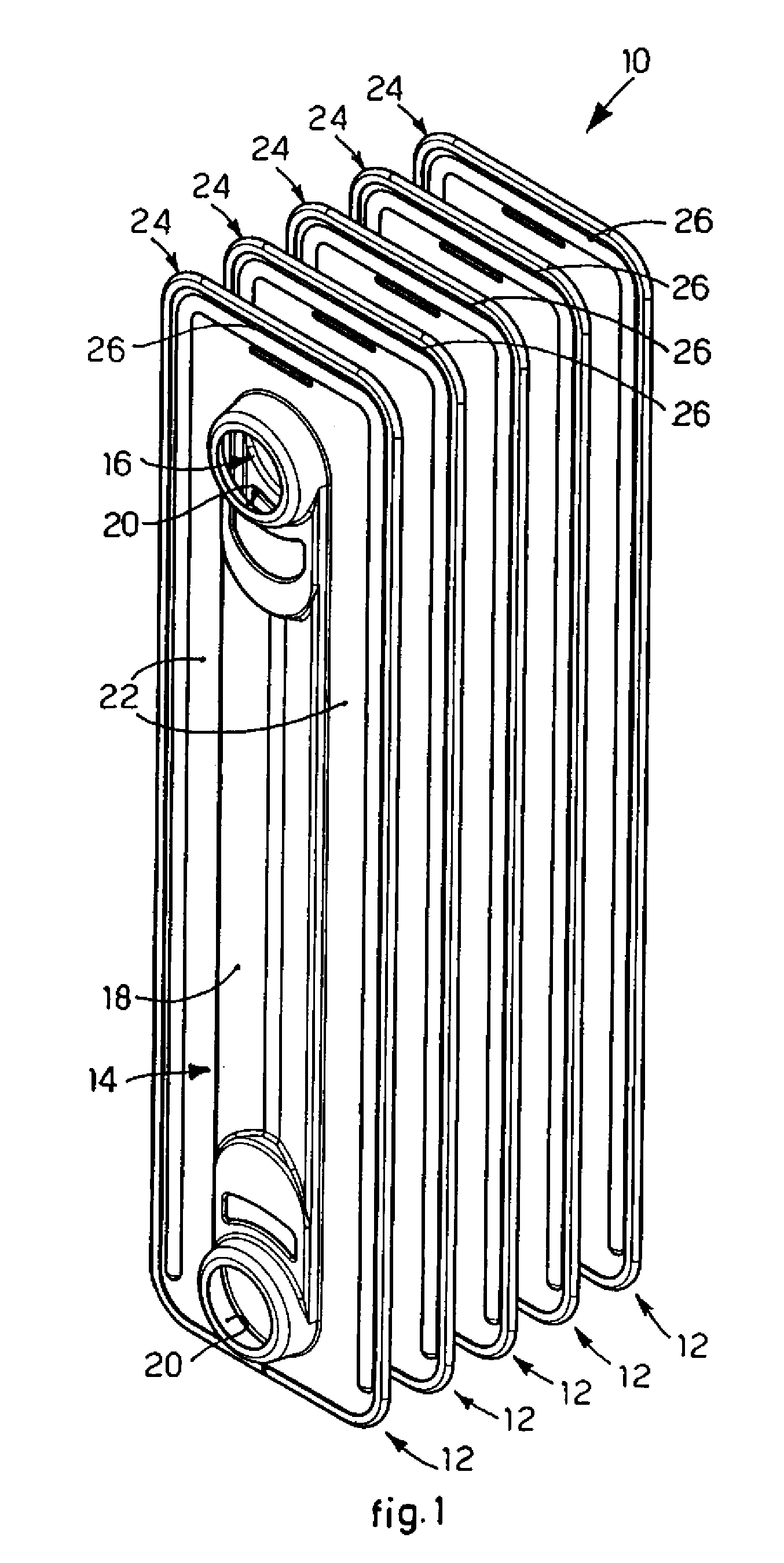
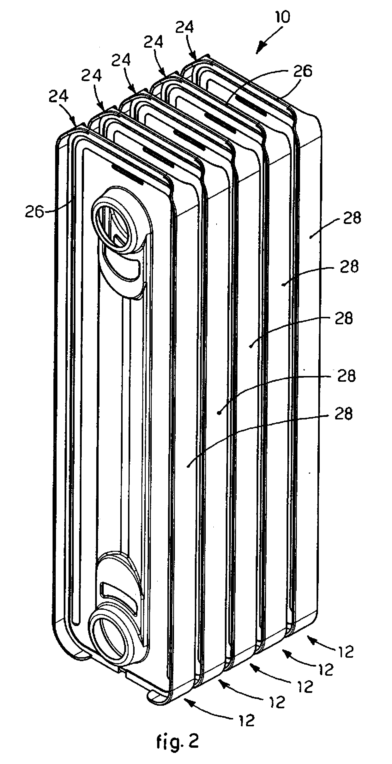
[0042]With reference to FIG. 1, a mobile device 10 is used for heating rooms.

[0043]The mobile device 10 comprises, in this case, five radiant elements 12, each one provided with two heat-conductor plates, respectively first 14 and second 16, associated with each other, for example by welding, so as to define a central portion 18 of the corresponding radiant element 12.

[0044]It is clear however that the mobile device 10 can have any number whatsoever of radiant elements 12.

[0045]The central portions 18 are connected fluid-dynamically with each other by means of collectors 20, upper and lower.

[0046]A heating means is provided, not shown, for example of the electric resistance type, able to heat a heat-carrying fluid, such as for example a diathermic oil.

[0047]The heat-carrying fluid is made to flow in the central portions 18 and, through the collectors 20, from one radiant element 12 to the other, to heat the air in the room.

[0048]Each pair of heat-conductor plates 14 and 16 comprises...


PUM


Abstract

A mobile device for heating rooms, comprising radiant elements, each provided with two heat-conductor plates associated with each other to define a central portion and connected fluid-dynamically with each other by means of connection elements. A heated heat-carrying fluid is able to flow in the central portions and, through the connection elements, from one to the other of the radiant elements in order to heat the surrounding room. Each pair of heat-conductor plates comprises lateral walls which are distanced from the corresponding central portion so as to define respective peripheral zones. The mobile device also comprises heat-insulating elements able to be applied due to having substantially the same shape so as to cover at least a part of the peripheral zones of the lateral walls.

Description

FIELD OF THE INVENTION[0001]The present invention concerns a mobile device for heating rooms comprising one or more radiant elements, in which a heat-carrying fluid flows.BACKGROUND OF THE INVENTION[0002]Mobile heating devices are known, such as for example heat radiators comprising one or more radiant elements, connected to each other and hydraulically communicating, each of which is defined by two metal plates connected in sealed manner with each other so as to define a central portion more or less extended with respect to the width of the plate.[0003]The central portions are normally connected hydraulically with each other by means of upper and lower collectors.[0004]A diathermic oil, heated by means of one or more electric resistances, is made to flow in the central portions and, through the collectors, from one radiant element to the other.[0005]In the field of mobile heating devices of this type, one of the problems generally faced is that of transmitting heat energy in the ro...

Claims


Application Information

Patent Timeline
IPC IPC(8): F24H9/00
CPCF24D19/06F24D2220/2018F24H3/004F28F2270/00F28D1/05358F28F1/14F24H9/02F28F2265/00F28F2275/085
Inventor ZANOLIN, SERGIOGRANDIN, FILIPPO
Owner DE LONGHI SPA
Why Eureka
Try Eureka