Ultrafine wire and manufacturing method thereof

Inactive Publication Date: 2010-08-12
YAZAKI CORP
View PDF9 Cites 2 Cited by
  • Summary
  • Abstract
  • Description
  • Claims
  • Application Information

AI Technical Summary

Benefits of technology

[0012]According to the above described exemplary embodiment, the conductor is manufactured by compressing the twisted three wires with the compressing die. The conductor is manufactured so that the ratio of a cross section of the conductor after compressing to an area of the compressing hole is 80% to 83%. The ultrafine wire provided with such a conductor less tend to be buckled during the terminal insertion into the connector housing. By adapting the manufacturing method of the above exemplary embodiment, the ultrafine wire obtains good workability for the terminal insertion and the buckling characteristics.
[0013]According to the above described exemplary embo

Problems solved by technology

The problem is that the ultrafine wire provided with a wire of the diameter smaller than 0.15 mm has a small buckling load.
On the other hand, the ultrafine wire 1 of small strength has bad workability for the terminal insertion.
There is a

Method used


Image

  • Ultrafine wire and manufacturing method thereof
  • Ultrafine wire and manufacturing method thereof
  • Ultrafine wire and manufacturing method thereof

Examples


Example

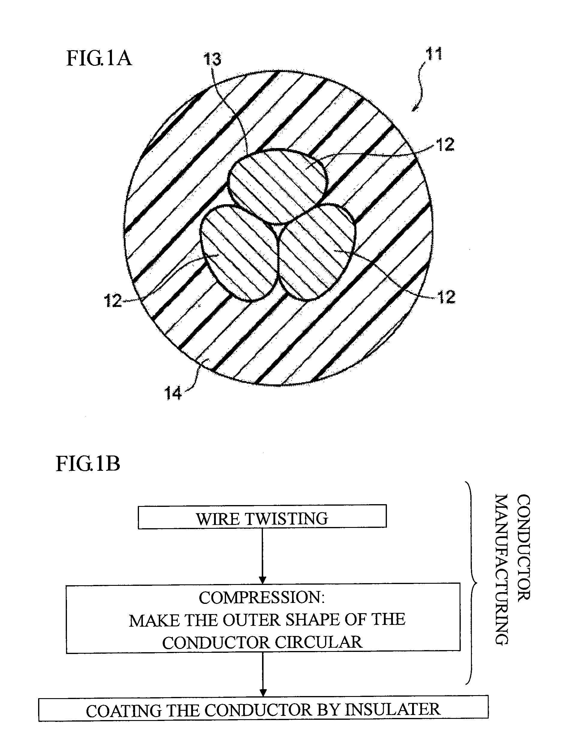
[0020]An exemplary embodiment of the present invention is described below with reference to drawings. FIGS. 1A and 1B show an exemplary embodiment of an ultrafine wire and a manufacturing method of the ultrafine wire according to the present invention. FIG. 1A is a cross sectional view of the ultrafine wire. FIG. 1B is a flow chart for the manufacturing method of the ultrafine wire.

[0021]FIG. 1A shows an ultrafine wire 11 of the exemplary embodiment. The ultrafine wire 11 is one component of a wire harness disposed in a vehicle such as an automobile and an example of a low voltage wire for the automobile. The ultrafine wire 11 is to be connected to a related terminal clasp (not shown) at an end thereof. The terminal clasp is one component of a connector. The connector is used for connecting the wire harness to an electronic parts or the like mounted on the vehicle. The terminal clasp is inserted into a space of a connector housing from rear side of the connector housing.

[0022]The ul...


PUM

PropertyMeasurementUnit
Fractionaaaaaaaaaa
Fractionaaaaaaaaaa
Percent by massaaaaaaaaaa

Abstract

A manufacturing method of an ultrafine wire including a conductor formed from a plurality of wire, the method comprising: twisting three wires into a twisted wires; and forming the conductor by compressing the twisted wires through a compressing hole of a compressing die after the twisting. A ratio of a cross section of the conductor after compressing to an area of the compressing hole is 80% to 83%.

Description

CROSS REFERENCE TO RELATED APPLICATIONS[0001]The present application claims foreign priority from Japanese Patent Application No. 2009-027180 filed on Feb. 9, 2009, and the subject matter of which is incorporated herein by reference.TECHNICAL FIELD[0002]The present invention relates to an ultrafine wire and a manufacturing method of a conductor for the ultrafine wire.BRIEF DESCRIPTION OF RELATED ART[0003]A wire harness is disposed in a vehicle body such as an automobile. The wire harness is manufactured by bundling wires which are connected to electronic parts or the like mounted on the vehicle body. The wires are respectively connected to a terminal clasp at the end thereof. The terminal clasp is received in a connector housing which is provided for connecting the terminal clasp to the electrical parts. There are a lot of kinds of wires. For example, an ultrafine wire having a conductor cross sectional area (nominal cross sectional area) of 0.13 sq is used for the wire harness. (se...

Claims


Application Information

Patent Timeline
IPC IPC(8): H01B5/08H01R43/00
CPCH01B13/0006H01B13/0292Y10T29/49117Y10T29/49195Y10T29/49197Y10T29/49071Y10T29/49194Y10T29/49199
Inventor YOSHINAGA, SATORUYAMADA, TOSHIYUKISUZUKI, TAKANORI
Owner YAZAKI CORP
Why Eureka
Try Eureka