Base board module

Inactive Publication Date: 2020-12-10
MITSUBISHI ELECTRIC CORP
View PDF0 Cites 1 Cited by
  • Summary
  • Abstract
  • Description
  • Claims
  • Application Information

AI Technical Summary

Benefits of technology

[0011]According to the present invention, since the coaxial connector is attached to the area in which the conductor is excluded over the entire edge of the printed circuit board, detailed design of the printed circuit board in consideration of an effect of the conductor of the edge on a characteristic

Problems solved by technology

In this base board module, when an electrode structure is different between the coaxial connector and the printed

Method used


Image

  • Base board module
  • Base board module
  • Base board module

Examples


first embodiment

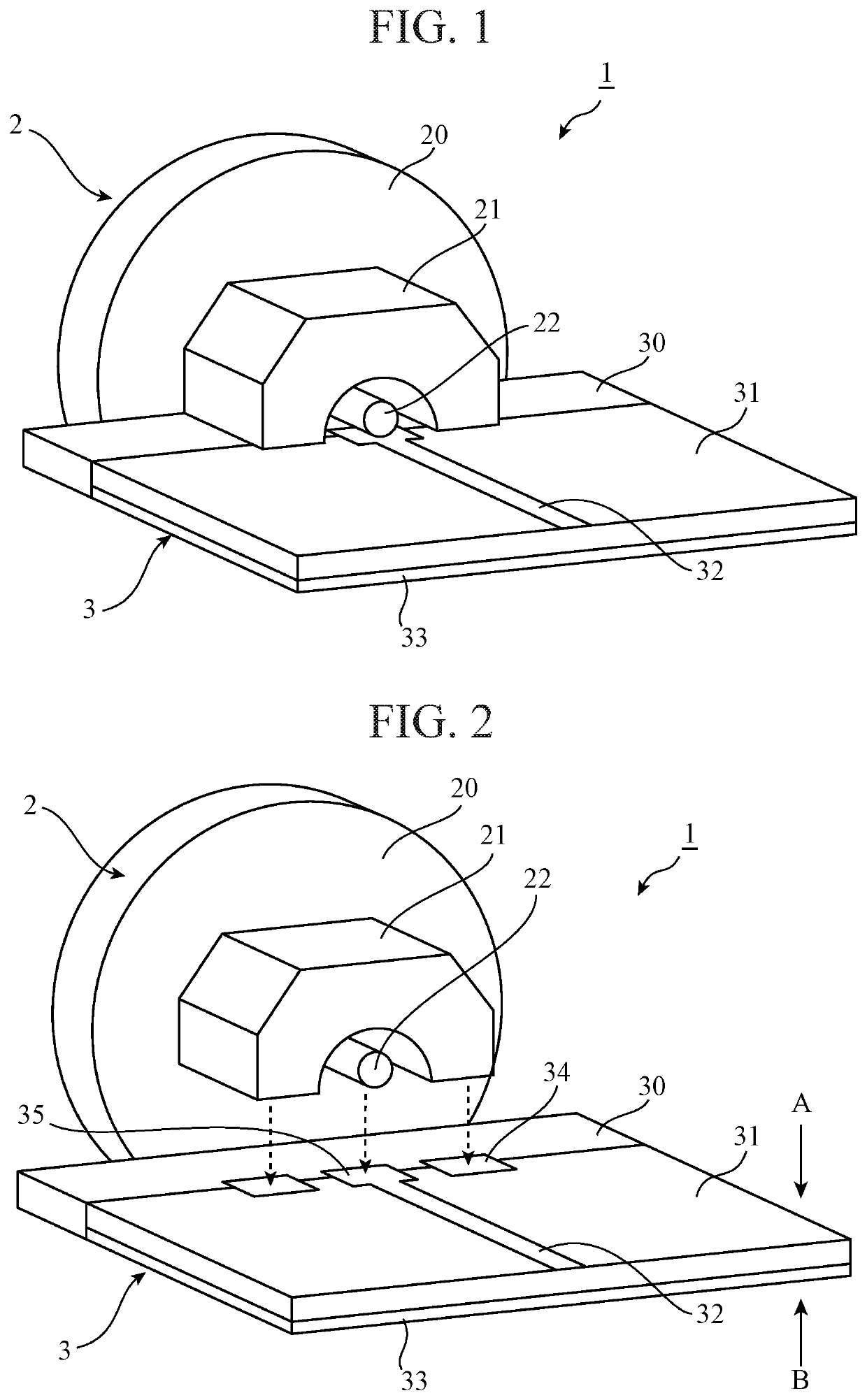
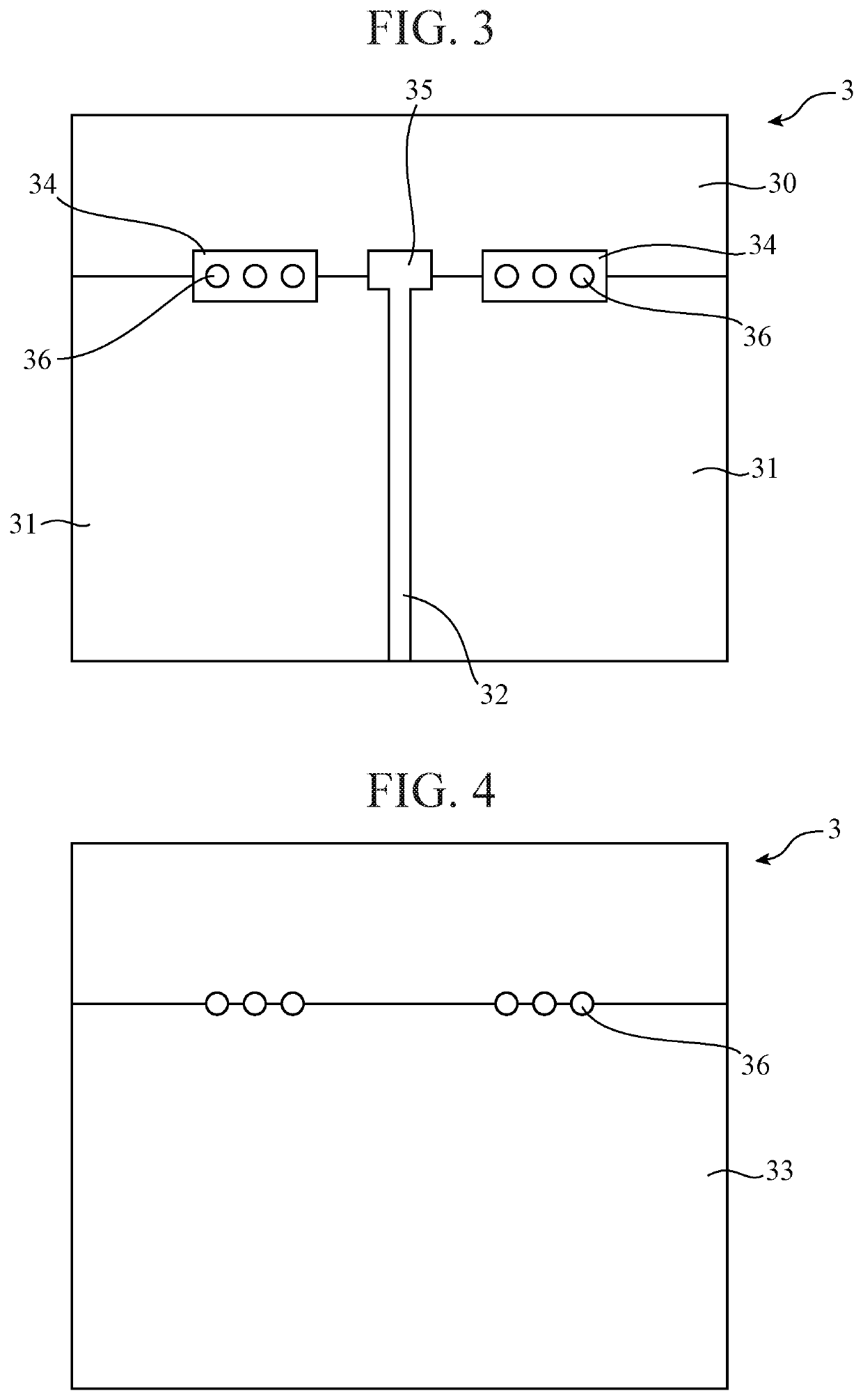
[0021]FIG. 1 is a perspective view illustrating a base board module 1 according to a first embodiment of the present invention. FIG. 2 is an exploded perspective view illustrating the base board module 1, illustrating a state in which a coaxial connector 2 is detached from a printed circuit board 3. The base board module 1 is provided with the coaxial connector 2 and the printed circuit board 3 as illustrated in FIG. 1. The coaxial connector 2 is provided with a first ground conductor portion 20, a second ground conductor portion 21, and a core wire 22. The printed circuit board 3 is provided with a conductor-less area 30, a wiring area 31, a signal wire 32, a base board ground 33, ground pads 34, and a signal pad 35.

[0022]In the coaxial connector 2, the first ground conductor portion 20 is a cylindrical conductor member with the core wire 22 provided inside thereof, and is electrically connected to a shield member (not illustrated) of a coaxial cable to have ground potential. The s...

second embodiment

[0047]FIG. 7 is a cross-sectional view illustrating a base board module 1A according to a second embodiment of the present invention, illustrating a cross-section of the base board module 1A taken in an axial direction. The base board module 1A is provided with a coaxial connector 2A and a printed circuit board 3 as illustrated in FIG. 7.

[0048]Similar to the first embodiment, the coaxial connector 2A has a structure in which a conductor member including a first ground conductor portion 20 and a second ground conductor portion 21 surrounds a core wire 22, but a first dielectric portion 23 is provided inside the second ground conductor portion 21.

[0049]As illustrated in FIG. 7, the first dielectric portion 23 includes dielectrics 230 to 232 having different relative permittivities. The dielectric 230 has the smallest relative permittivity, and the dielectric 231 has the largest relative permittivity. The dielectric 232 has an intermediate relative permittivity between those of the die...

third embodiment

[0059]FIG. 8 is a cross-sectional view illustrating a base board module 1B according to a third embodiment of the present invention, illustrating a cross-section of the base board module 1B taken in an axial direction. The base board module 1B is provided with a coaxial connector 2B and a printed circuit board 3 as illustrated in FIG. 8.

[0060]Similar to the first embodiment, the coaxial connector 2B has a structure in which a conductor member including a first ground conductor portion 20 and a second ground conductor portion 21 surrounds a core wire 22, but a second dielectric portion 24 is provided inside the first ground conductor portion 20.

[0061]As illustrated in FIG. 8, the second dielectric portion 24 includes dielectrics 240 to 242 having different relative permittivities. The dielectric 240 has the smallest relative permittivity, and the dielectric 241 has the largest relative permittivity. The dielectric 242 has an intermediate relative permittivity between those of the die...


PUM


Abstract

A printed circuit board (3) includes a conductor-less area (30) in which a conductor is excluded over an entire edge on a side to which a coaxial connector (2) is attached. An end of a core wire (22) is brought into contact with a signal pad (35) in a state of being covered with a second ground conductor portion (21) of the coaxial connector (2) attached to the conductor-less area (30).

Description

TECHNICAL FIELD[0001]The present invention relates to a base board module provided with a printed circuit board on which a coaxial connector is mounted.BACKGROUND ART[0002]Conventionally, a coaxial connector is often used to keep a good transmission characteristic in transmission of a high frequency signal a frequency of which exceeds GHz.[0003]As a usage mode of the coaxial connector, there is a base board module in which the coaxial connector is attached to an edge of a printed circuit board. In this base board module, when an electrode structure is different between the coaxial connector and the printed circuit board, the transmission characteristic is degraded due to unmatched reflection in a high frequency domain.[0004]For example, an attachment disclosed in Patent Literature 1 is a base board module in which a coaxial connector is covered with a conductive cover, and a quasi-coaxial transmission line is provided on a surface layer of a circuit board on which the coaxial connec...

Claims


Application Information

Patent Timeline
IPC IPC(8): H01R24/50H01R12/72H01R13/6594
CPCH01R24/50H01R12/722H01R13/6594H01R24/42
Inventor OKANAMI, YUKIITAKURA, HIROSHIAKEBOSHI, YOSHIHIRO
Owner MITSUBISHI ELECTRIC CORP
Why Eureka
Try Eureka