Multi-frequency band antenna device for radio communication terminal

a radio communication terminal and multi-frequency band technology, applied in the direction of antennas, antenna details, electrically short antennas, etc., can solve the problems of insufficient high-band bandwidth, inconvenient implementation, and reduced performance of multi-layer designs with capacitive coupling proposed by ying, and achieve significant bandwidth and advantageous performance.

Active Publication Date: 2009-01-13
SONY CORP
View PDF10 Cites 195 Cited by
  • Summary
  • Abstract
  • Description
  • Claims
  • Application Information

AI Technical Summary

Benefits of technology

[0031]Some embodiments of the invention may provide for significant bandwidth in high-bands without the use of expensive ceramic components.
[0032]Some embodiments of the invention may provide for advantageous performance in a small volume, which for instance allows for small, more attractive phones.

Problems solved by technology

However, the multi-layer design with capacitive coupling proposed by Ying has somewhat reduced performance in the low-bands and does not have sufficient bandwidth in the high-bands, for instance to achieve a suitable digital cellular service (DCS) / personal communication service (PCS) / universal mobile telecommunications system (UMTS) performance.
Additionally, the cost of implementation can be prohibitive due to the elevated costs of the specialized ceramic materials, as specific dielectric pellets made of a highly specialized ceramic material are needed.

Method used


Image

  • Multi-frequency band antenna device for radio communication terminal
  • Multi-frequency band antenna device for radio communication terminal
  • Multi-frequency band antenna device for radio communication terminal

Examples


Embodiment Construction

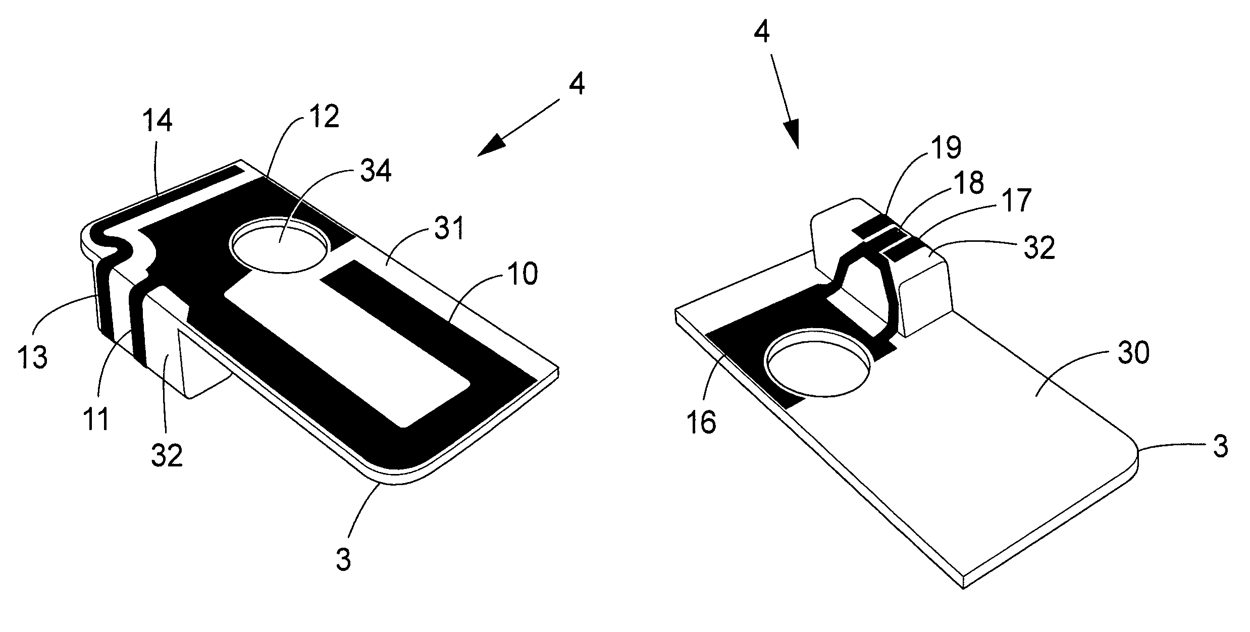
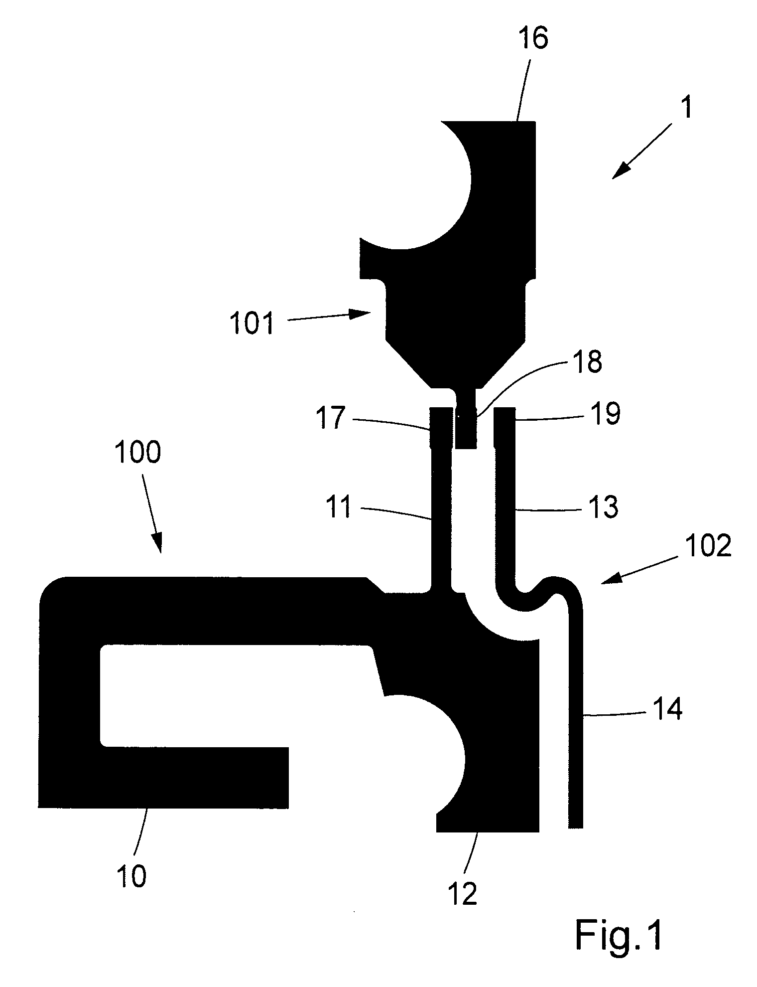
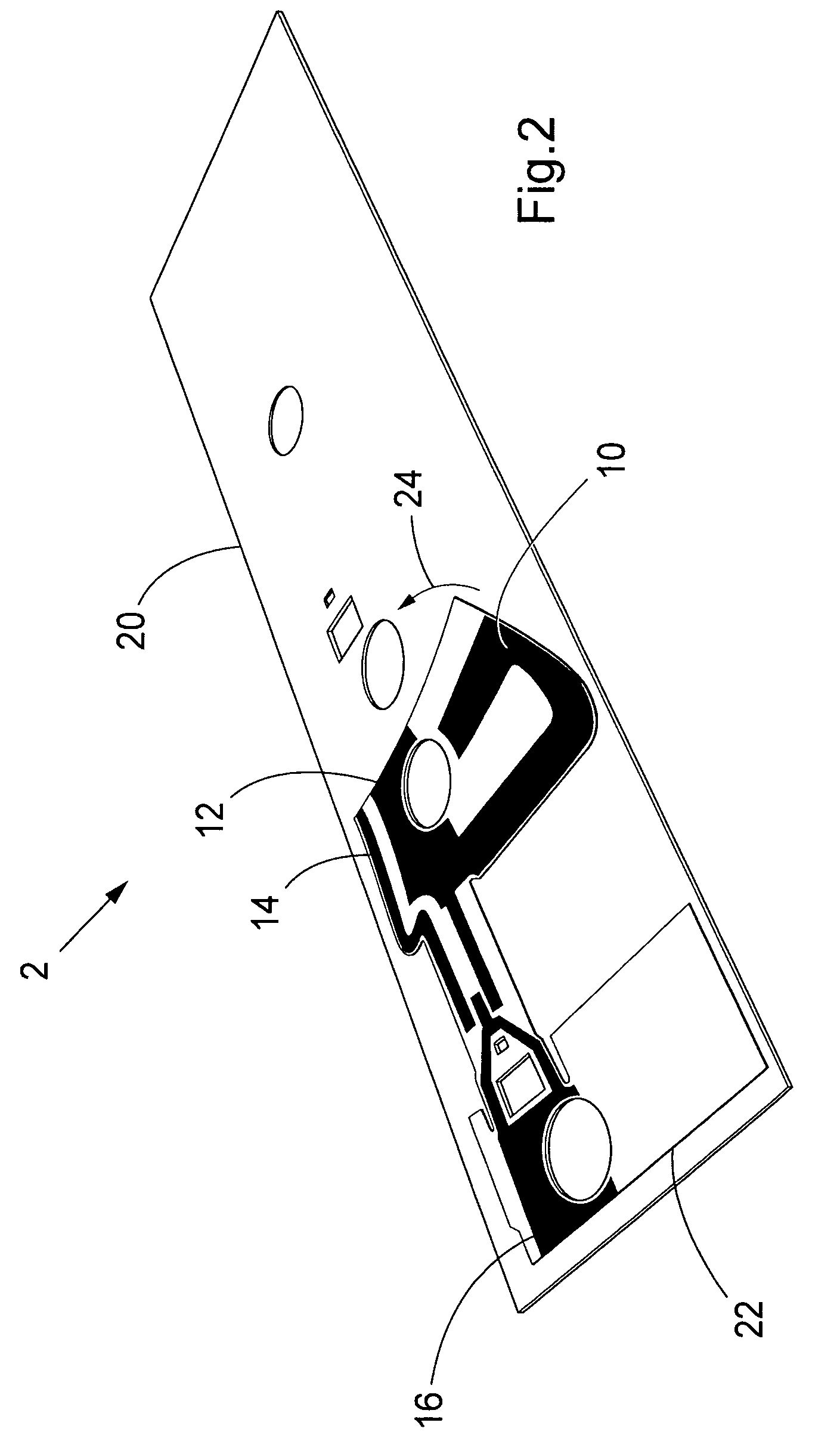
[0042]It will be understood that the figures, illustrating an exemplary embodiment of the invention, are merely schematic and are not drawn to scale. For clarity of illustration, certain dimensions may have been exaggerated while other dimensions may have been reduced. Also, where appropriate, the same reference numerals and letters are used throughout the figures to indicate the same parts and dimensions.

[0043]The following description focuses on an embodiment of the present invention applicable to a mobile telephone. However, it will be appreciated that the invention is not limited to this application, but may be applied to many other mobile communication terminals in which to implement a radio antenna design according to embodiments of the invention, including the following examples. The terms mobile or radio communication terminal comprise all mobile equipment devised for radio communication with a radio station, which radio station also may be a mobile terminal or, e.g., a stat...


PUM


Abstract

A multi-band radio antenna device for a radio communication terminal includes an integral feed and ground structure electrically connected to a first radiating antenna element and a second radiating antenna element. The first radiating antenna element includes a first continuous trace of conductive material, wherein the first continuous trace has a first branch tuned to radiate at first frequencies in a first frequency band, and a second branch, which is tuned to radiate in a second frequency band at second frequencies approximately equal to or greater than two times the first frequencies. The said second radiating antenna element has a second continuous trace of conductive material, wherein the second continuous trace has a third branch capacitively coupled to the second branch. Such an antenna device is suitable for built-in antennas, at the same time having a wide high-frequency band bandwidth, which enables the antenna to be operable at a number of frequency bands.

Description

RELATED APPLICATIONS[0001]This application claims priority under 35 U.S.C. § 119 based on U.S. Provisional Application Ser. No. 60 / 779,427, filed Mar. 7, 2006, the disclosure of which is incorporated herein by reference.FIELD OF THE INVENTION[0002]This invention pertains in general to the field of antennas for radio communication terminals and, in particular, to compact multi-frequency band antennas devised to be incorporated or built-in into mobile or portable radio communication terminals and having a wide high-bandwidth to facilitate operation of such terminals.BACKGROUND OF THE INVENTION[0003]The use of radio communication networks is rapidly becoming a part of the daily life for more and more people around the globe. For instance, the GSM (Global System for Mobile Communications) networks offer a variety of functions. Generally, radio communication systems based on such networks use radio signals transmitted by a base station in the downlink over the traffic and control channel...

Claims


Application Information

Patent Timeline
Patent Type & Authority Patents(United States)
IPC IPC(8): H01Q1/38H01Q5/371H01Q5/378
CPCH01Q9/0457H01Q5/378H01Q5/371
Inventor VANCE, SCOTT LA DELL
Owner SONY CORP
Why Eureka
Try Eureka