Ultrasonic shear with asymmetrical motion

a technology of asymmetric motion and ultrasonic shear, which is applied in the field of ultrasonic devices, can solve the problems of limited ability of single-element end-effector instruments to apply blade-to-tissue pressure, less-than-desired hemostasis and tissue joining, and the use of other ultrasonic surgical instruments

Active Publication Date: 2009-01-20
CILAG GMBH INT
View PDF62 Cites 422 Cited by
  • Summary
  • Abstract
  • Description
  • Claims
  • Application Information

AI Technical Summary

Problems solved by technology

While such instruments as disclosed in U.S. Pat. No. 5,263,957 have been found eminently satisfactory, there are limitations with respect to their use, as well as the use of other ultrasonic surgical instruments.
For example, single-element end-effector instruments have limited ability to apply blade-to-tissue pressure when the tissue is soft and loosely supported.
This inability to grasp the tissue results in a further inability to fully coapt tissue surfaces while applying ultrasonic energy, leading to less-than-desired hemostasis and tissue joining.
Generally, however, the Balamuth device, as disclosed in those patents, may not coagulate and cut sufficiently fast, and may lack versatility in that it cannot be used to cut / coagulate without the clamp because access to the blade is blocked by the clamp.
Although ultrasonic shears such as, those disclosed in U.S. Pat. Nos. 5,322,055 and 5,893,835 have been found satisfactory, there may be limitations with respect to their use.
End-effectors of devices that operate in primarily longitudinal mode exhibit a sinusoidally diminishing effectiveness proximally from the distal end of the end-effector.
This currently limits the effective length of ultrasonic devices to a fraction of their wavelength, usually substantially less that ¼ wavelength, to stay away from the node at ¼ wavelength.

Method used


Image

  • Ultrasonic shear with asymmetrical motion
  • Ultrasonic shear with asymmetrical motion
  • Ultrasonic shear with asymmetrical motion

Examples


Embodiment Construction

[0037]In the following description of the illustrated embodiments, references are made to the accompanying drawings, which form a part hereof, and in which is shown by way of illustration various embodiments in which the invention may be practiced. It is to be understood that other embodiments may be utilized, and structural and functional changes may be made without departing from the scope of the present invention.

[0038]In an ultrasonic device running at resonance in longitudinal mode, the longitudinal ultrasonic motion, d, behaves as a simple sinusoid at the resonant frequency as given by:

d=A sin

[0039]where:

[0040]ω=the radian frequency which equals times the cyclic frequency, f; t is time; and A=the zero-to-peak amplitude.

[0041]The longitudinal excursion is defined as the peak-to-peak (p-t-p) amplitude, which is just twice the amplitude of the sine wave or 2A.

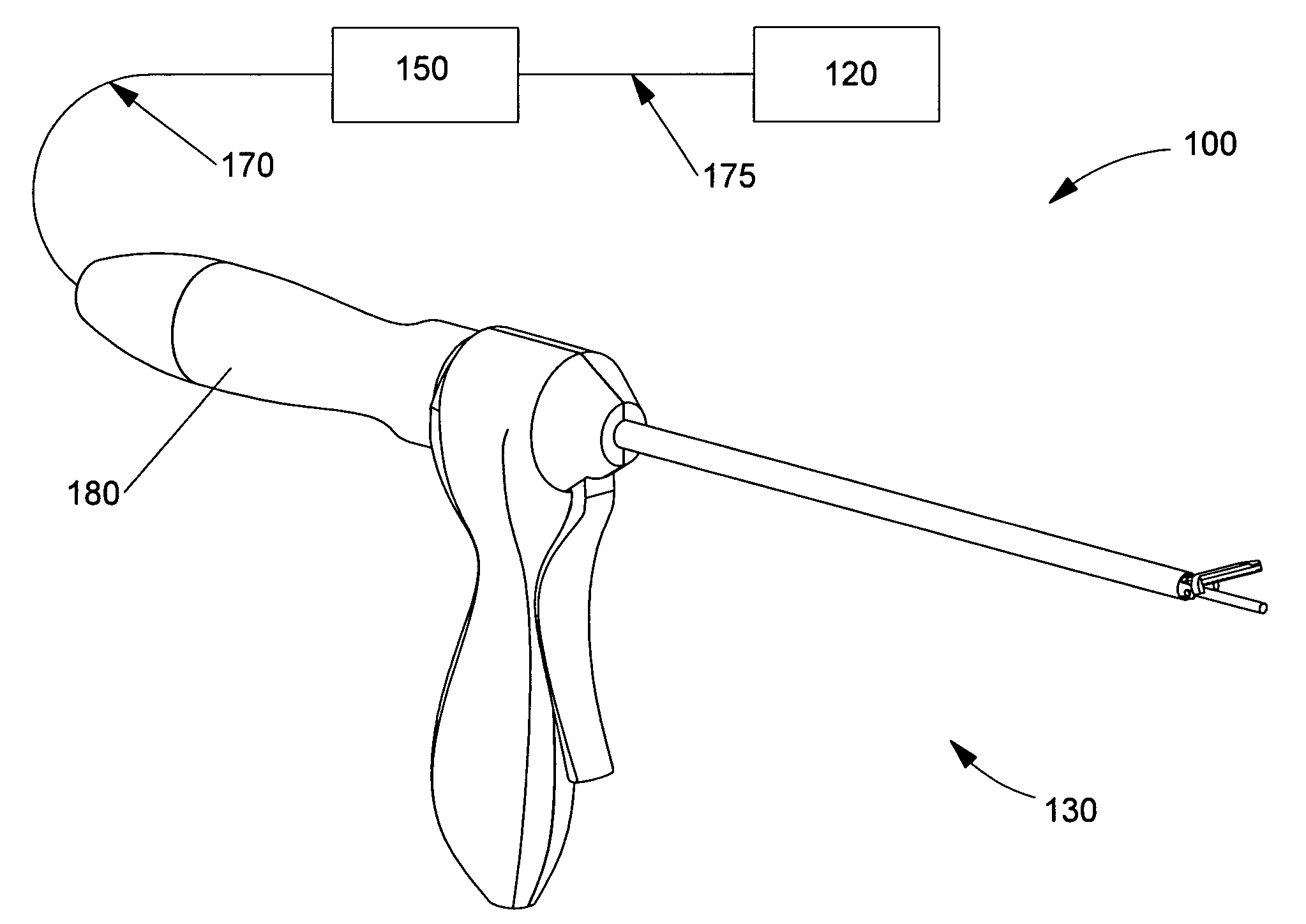
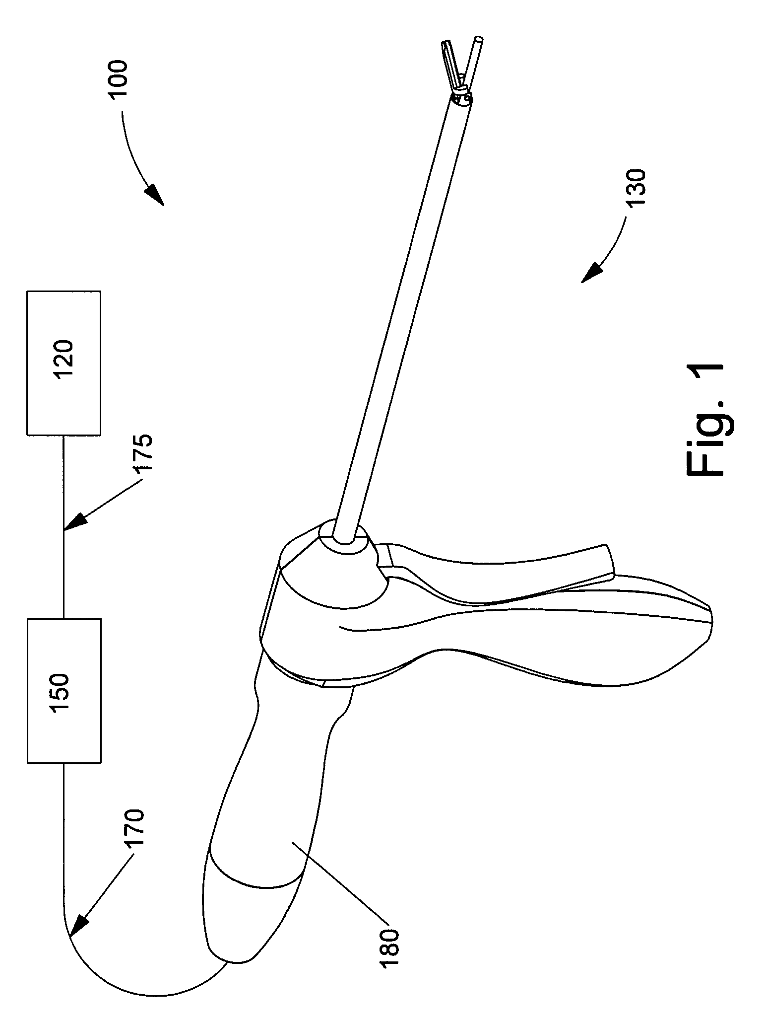
[0042]Referring now to FIG. 1, a perspective view of an ultrasonic shear system 100 is illustrated in accordance with embo...


PUM


Abstract

Devices providing ultrasonic clamped cutting using asymmetrical motion include a housing and ultrasonic waveguide. A longitudinal axis extends through the center of mass of the ultrasonic waveguide. An actuating assembly provides opposable movement of a clamp arm with respect to the cutting blade, the movement defining a vertical plane having a vertical axis orthogonal to both the longitudinal axis and a horizontal axis. An end-effector coupled to the ultrasonic waveguide includes a cutting blade that cuts using ultrasonic motion. The blade's center of mass may be offset from the longitudinal axis, providing motion of the blade in both the longitudinal and vertical axes concurrently. Excursion of the cutting blade in the direction of the horizontal axis that may be limited to less than 92%, and in the direction of the vertical axis of more than 8%, of an excursion of the cutting blade in the direction of the longitudinal axis.

Description

[0001]This application claims the benefit of Provisional Patent Application Ser. No. 60 / 625,885, filed on Nov. 8, 2004, to which priority is claimed pursuant to 35 U.S.C. §119(e) and which is hereby incorporated herein by reference.BACKGROUND OF THE INVENTION[0002](a) Field of the Invention[0003]The present invention relates, in general, to ultrasonic devices and, more particularly, to methods and devices that provide ultrasonic clamped cutting using asymmetrical motion.[0004](b) Description of the Prior Art[0005]The fields of ultrasonics and stress wave propagation encompass applications ranging from non-destructive testing in materials science, to beer packaging in high-volume manufacturing. Diagnostic ultrasound uses low-intensity energy in the 0.1-to-20-MHz region to determine pathological conditions or states by imaging. Therapeutic ultrasound produces a desired bio-effect, and can be divided further into two regimes, one in the region of 20 kHz to 200 kHz, sometimes called low...

Claims


Application Information

Patent Timeline
Patent Type & Authority Patents(United States)
IPC IPC(8): A61B17/32
CPCA61B17/320092A61B2017/00238A61B2017/0084A61B2017/22015A61B2017/320095A61B2017/320093A61B2017/320094
Inventor BEAUPRE, JEAN
Owner CILAG GMBH INT
Why Eureka
Try Eureka