Tape measure weight

a technology of metal rollup tape and weight, which is applied in the direction of measuring devices, instruments, and using mechanical means, etc., can solve the problems of relatively easy buckles, relatively stiff tapes, and difficult to make precise measurements of distances greater than, and achieve easy and reliable formation, high quality, and low cost.

Inactive Publication Date: 2009-02-10
COOPER JASON D
View PDF20 Cites 44 Cited by
  • Summary
  • Abstract
  • Description
  • Claims
  • Application Information

AI Technical Summary

Benefits of technology

[0017]Another object of the present invention is to provide a tape measure weight which rests against a surface at a reference location and provide a very precise measurement of a distance away from the reference location.
[0018]Another object of the present invention is to provide a tape measure weight which is sufficiently heavy to resist significant movement when common wind loads are encountered by the tape.
[0019]Another object of the present invention is to provide a tape measure weight which can be easily and reliably formed from commonly available materials in a high quality low cost fashion.

Problems solved by technology

This curvature makes the tape relatively stiff and difficult to buckle in one direction, but can relatively easily buckle in an opposite direction.
One problem with common metal tapes is the difficulty associated with making precise measurements of distances greater than about eight to twelve feet when a user is utilizing the tape without a partner.
However, as measurements grow increasingly longer, the user is often frustrated by an inability to precisely locate the clasp at the reference location and keep the tip of the tape at this reference location until the measurement can be successfully taken.
One common scenario often encountered, especially by construction workers is the difficulty associated with making vertical measurements especially when the user is measuring downward from above down toward a reference surface.

Method used


Image

  • Tape measure weight
  • Tape measure weight
  • Tape measure weight

Examples


Embodiment Construction

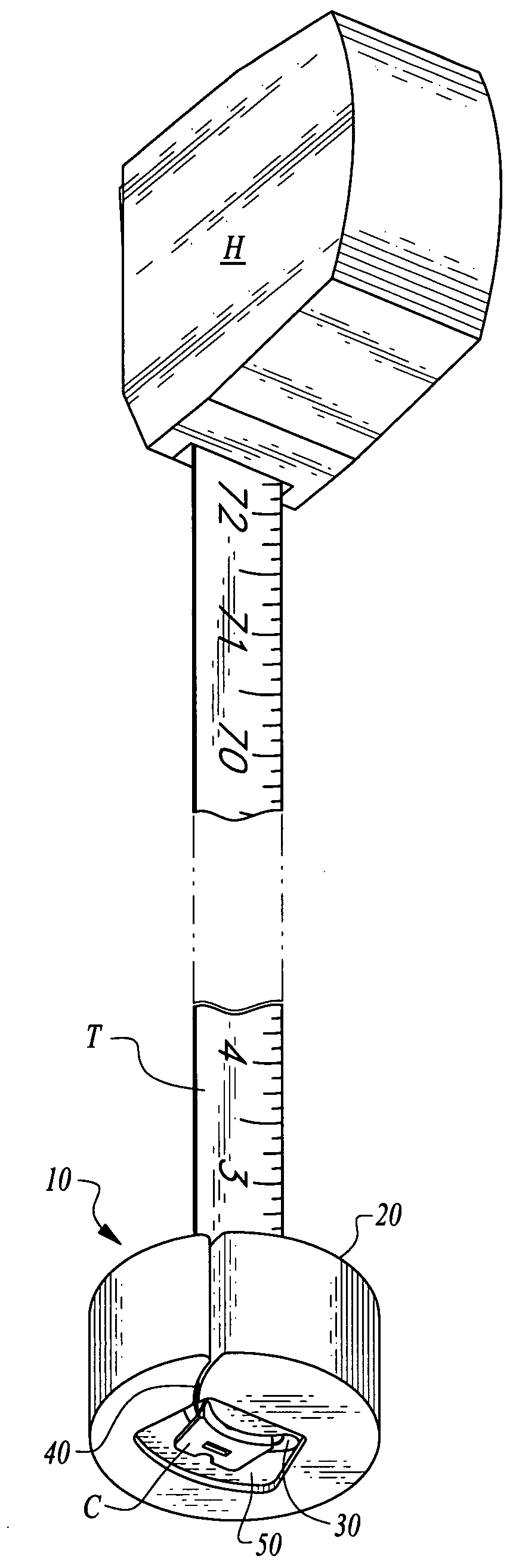
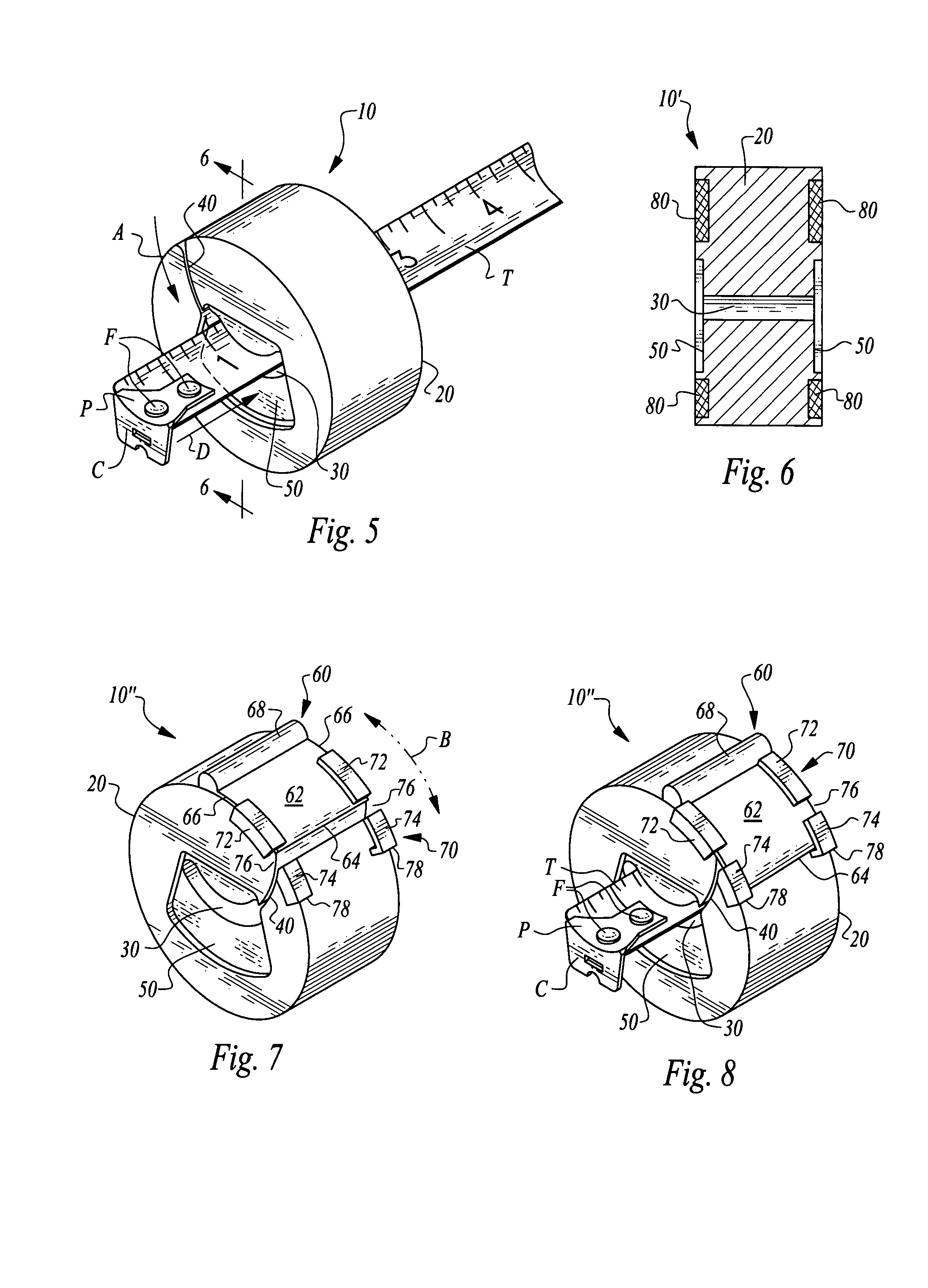
[0029]Referring to the drawings, wherein like reference numerals represent like parts throughout the various drawing figures, reference numeral 10 is directed to a tape measure weight (FIG. 1) which is attachable to a tip of a tape T, adjacent a clasp C, especially to keep the tape T steady while taking measurements in a vertical downward direction. The tape measure weight 10 has a mass significantly greater than a mass of the tape T so that wind loads and other lateral forces applied to the tape T do not provide significant movement of the tape T during the taking of vertical downward measurements with the tape T.

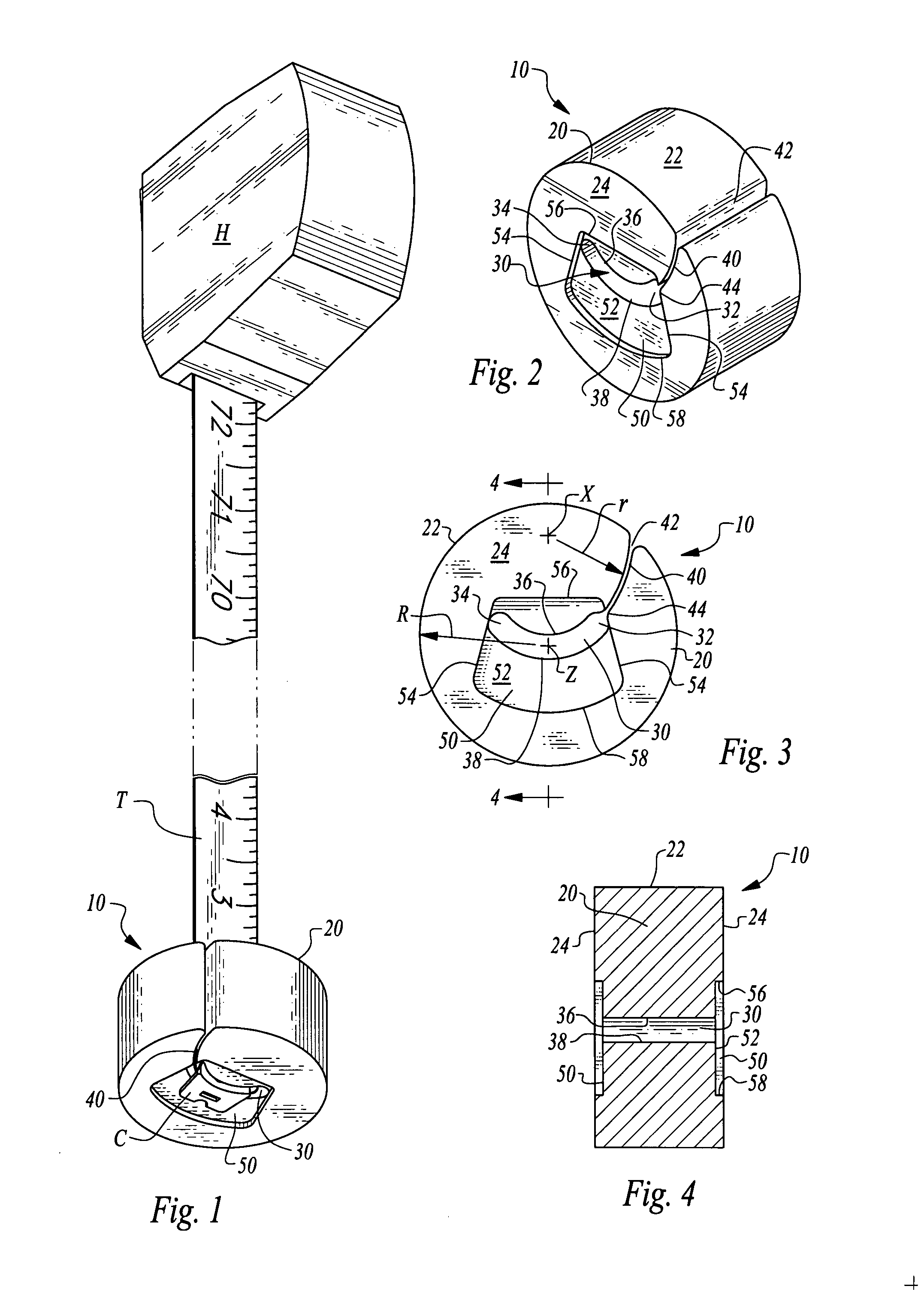
[0030]In essence, and with particular reference to FIGS. 1-4, basic details of the tape measure weight 10 of this invention are described according to a preferred embodiment. The tape measure weight 10 is primarily formed of a body 20 having a cavity 30 formed therein and passing entirely therethrough (FIG. 4). This cavity 30 receives the clasp C of the tape T therein such...


PUM


Abstract

A weight is provided for attachment to a tip of a tape measure and to facilitate stabilization of the tip when extending far from a housing thereof. The weight includes a cavity passing through a high mass body with a slot extending between the cavity and an exterior of the body. The slot is configured to allow the tape to pass therethrough, to enter the cavity. The cavity is sized to allow a clasp at a tip of the tape to reside therein. The slot is preferably curved to match a curvature of a common metal roll-up tape measure. A recess can be provided on the body adjacent the cavity to accommodate a portion of the clasp of the tape therein. Magnets can optionally be provided on the body to allow the weight to be attachable to ferromagnetic surfaces. A door can optionally be provided which selectively closes the slot.

Description

FIELD OF THE INVENTION[0001]The following invention relates to common metal roll-up tape measures, such as those which are often used in construction trades, and which typically measure approximately twenty-five feet in length with a curving cross-section. More particularly, this invention relates to accessories for metal roll-up tape measures, and particularly accessories attachable to a tip of such metal roll-up tape measures.BACKGROUND OF THE INVENTION[0002]When measurements are to be made, especially within the construction trades, a most common prior art tool utilized for such measurements is a metal roll-up tape measure. Such common metal tapes are particularly useful when measuring relatively short distances, and particularly distances of twenty-five feet or less, where the tape measure is not particularly bulky, but rather can be easily worn upon a belt or tool belt of a construction worker or other user. Such common metal tapes typically include a housing which contains the...

Claims


Application Information

Patent Timeline
Patent Type & Authority Patents(United States)
IPC IPC(8): G01B3/10
CPCG01B3/1056G01B2003/1079
Inventor COOPER, JASON D.
Owner COOPER JASON D
Why Eureka
Try Eureka