Movable conveyor for loading a container

a conveyor and container technology, applied in the direction of refuse receptacles, transportation items, applications, etc., can solve the problems of insatiable generalization, difficult loading of the tank of the seeder, and limited movement of the hopper

Inactive Publication Date: 2009-02-10
DECKER COLONY FARMS
View PDF8 Cites 59 Cited by
  • Summary
  • Abstract
  • Description
  • Claims
  • Application Information

AI Technical Summary

Benefits of technology

[0019]to allow the conveyor duct to pivot about a horizontal axis transverse to the duct such that the conveyor duct can change in angle relative to the arm portion as the arm portion raises and lowers and such that, with the hopper resting on the ground and the arm portion extending outwardly from the side of the container, raising of the arm portion causes the hopper to be pulled in toward the container while lifting the upper end of the conveyor duct upward;

Problems solved by technology

The loading of the tank of a seeder has become more difficult in recent years due to the increase in size of the container or tank, due to the difficulty of reaching the loading opening of the tank and due to the current use of belly-dump trailers rather than the conventional lift trailer.
However these arrangements are generally limited to arcuate movement by virtue of vertical pivot axes so that the hopper is limited in its movement.
While this is acceptable for a trailer of the type which dumps at the rear, so that the trailer can be backed up to the hopper, it is not acceptable or raises significant difficulties in the event that it is required to unload the trailer from the center or from a belly-mount discharge opening since the trailer and its tractor are difficult to maneuver, since the seeder itself can not be maneuvered in the field and since the loading conveyor has limited movement.
Other arrangements have been proposed to overcome this problem but they are very expensive including providing conveyors mounted on the trailer itself.
These have generally not been satisfactory.

Method used


Image

  • Movable conveyor for loading a container
  • Movable conveyor for loading a container
  • Movable conveyor for loading a container

Examples


Embodiment Construction

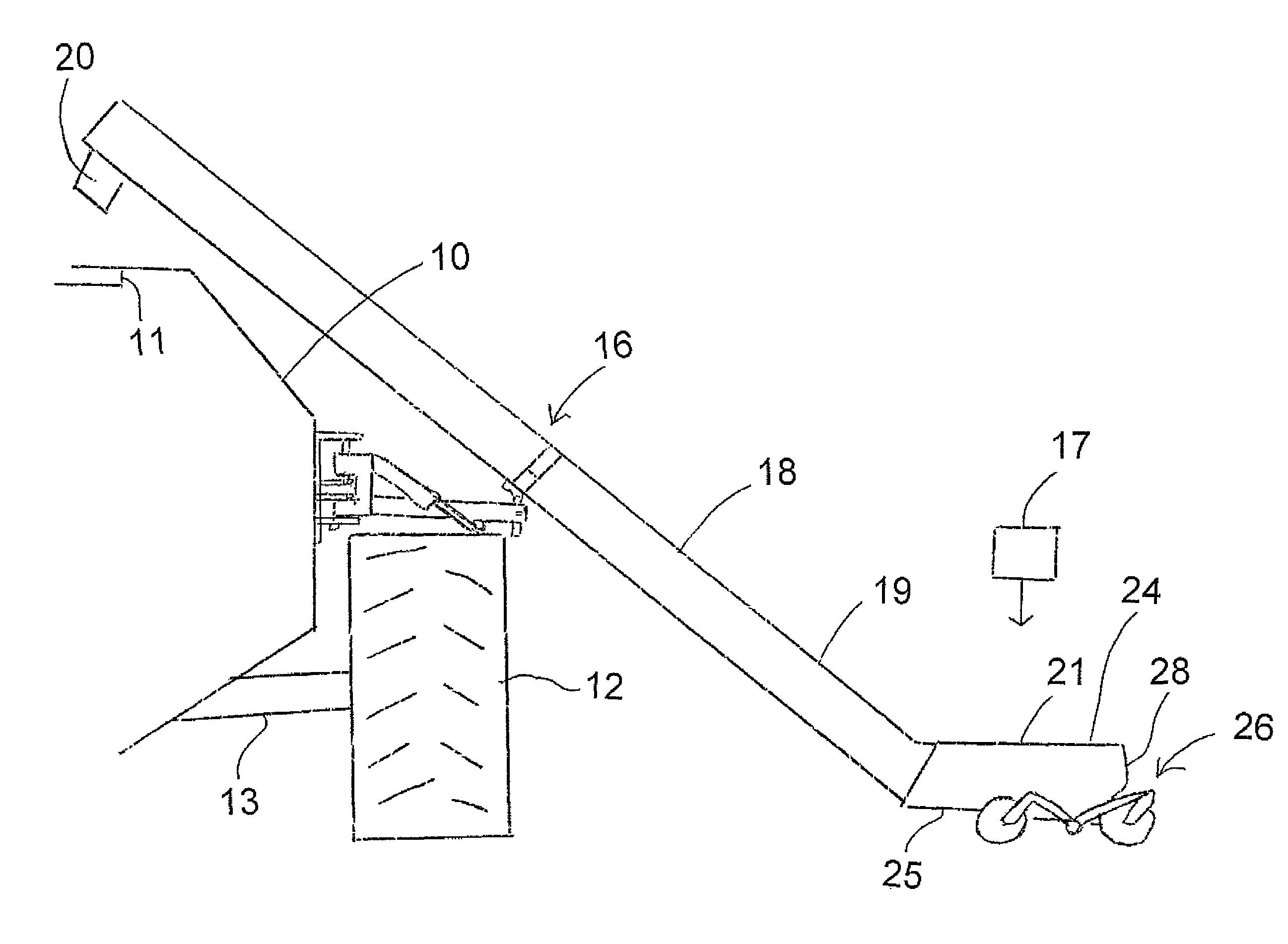
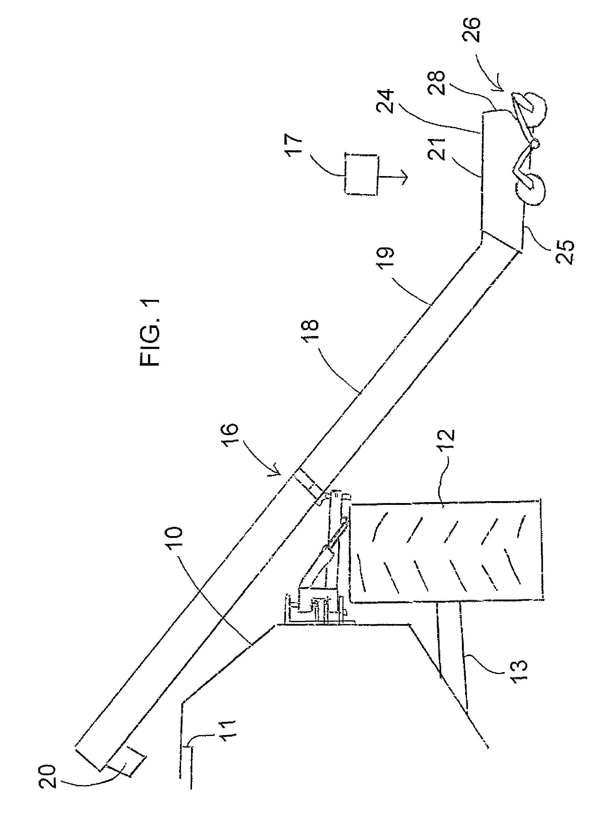
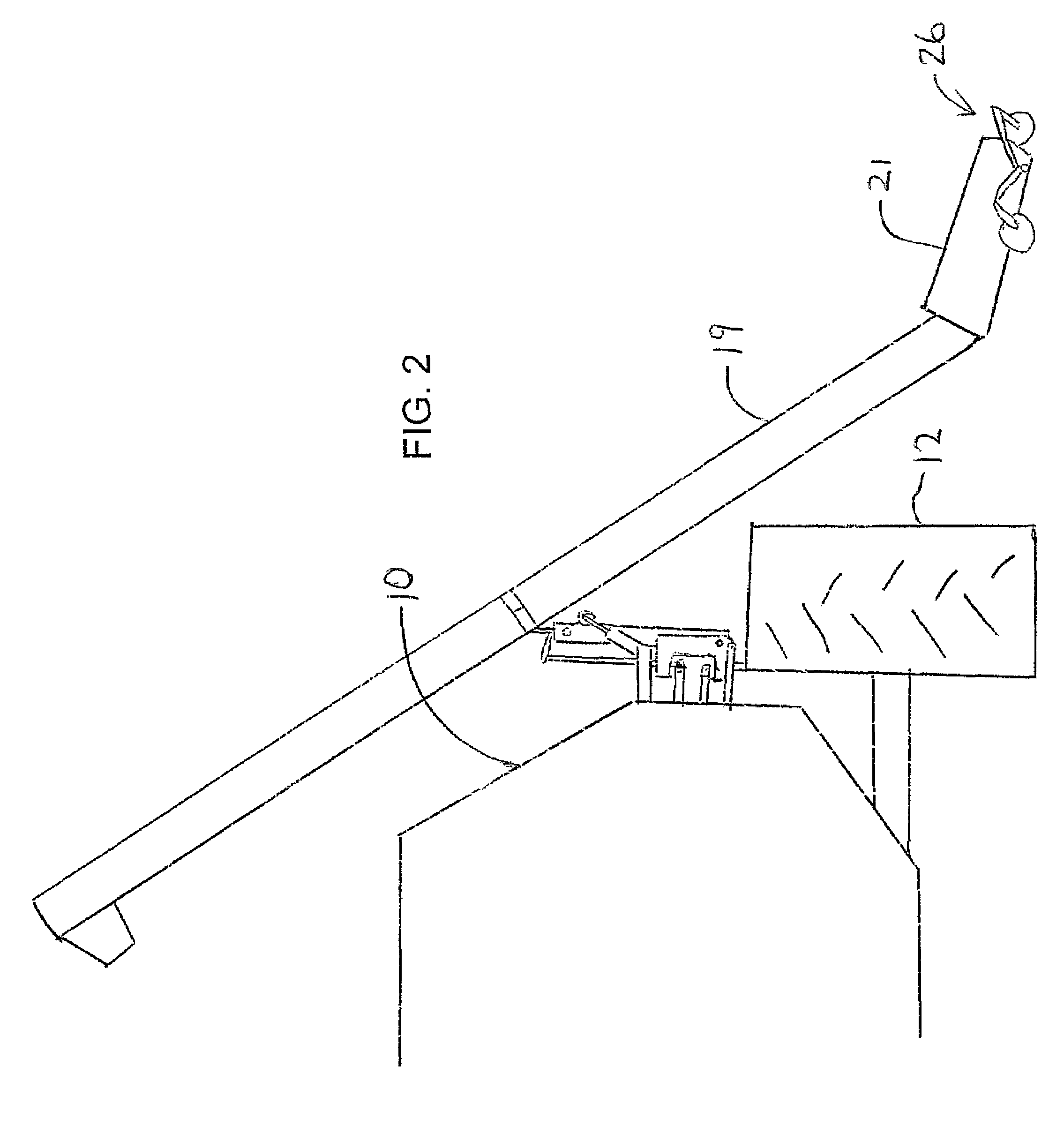
[0049]A tank 10 of a seeder includes a top opening 11 through which the tank can be filled. The tank is mounted on ground wheels 12 at respective sides of the tank carried on an axle 13. The tank is towed by a hitch 15 (FIG. 6) at a suitable location relative to the seeder. The apparatus of the present invention provides a loading device generally indicated at 16 for loading seed materials from a supply location generally indicated at 17 through a conveyor 18 into the opening 11. The conveyor 18 includes a duct 19 which has a discharge spout 20 at the upper end and a hopper 21 at the lower end.

[0050]The conveyor duct is generally tubular and contains a conveyor member driven by suitable drive mechanisms (not shown). The conveyor member is commonly in the form of an auger flight but may be replaced by a belt or in some cases both a belt and a flight are used. Other transport elements may also be used since the operation of the conveyor itself is not part of the present invention and ...


PUM


Abstract

A container for example for a seeder includes a filling conveyor mounted on one with a bottom hopper and an upper filling spout with the conveyor being movable in a direction inwardly and outwardly relative to the side of the container to different positions relative to the container for cooperation with a supply. This is achieved by mounting the conveyor on a swivel coupling at the outer end of an arm which can be raised and lowered by pivotal movement about an inner end at the container. The hopper is supported on two pairs of ground wheels, each pair being arranged on a respective side of the hopper for supporting the respective side and each pair comprising a respective one of a pair of castor wheels mounted at respective ends of a pivotal beam extending along the respective side of the hopper and pivotal about an axis transverse to the hopper.

Description

[0001]This invention relates to an apparatus including a movable conveyor movable to allow the hopper of the conveyor to be moved to positions to cooperate with a supply vehicle.BACKGROUND OF THE INVENTION[0002]The loading of the tank of a seeder has become more difficult in recent years due to the increase in size of the container or tank, due to the difficulty of reaching the loading opening of the tank and due to the current use of belly-dump trailers rather than the conventional lift trailer.[0003]Various arrangements have been used to resolve this problem and many seeder tanks now carry a loading mechanism in the form of a conveyor which is mounted on a suitable mounting assembly at the side of the tank. Generally the conveyor duct is mounted at the end of an arm which can swivel side to side without a vertical axis and the duct itself can also swivel about a pin at the end of the arm so that the location of the hopper at the lower end of the duct can be maneuvered to different...

Claims


Application Information

Patent Timeline
Patent Type & Authority Patents(United States)
IPC IPC(8): B60P1/52
CPCA01C15/003B65G41/002
Inventor WALDNER, SAMUEL
Owner DECKER COLONY FARMS
Why Eureka
Try Eureka