
Polarization and reflection based non-contact latent fingerprint imaging and lifting

a technology of latent fingerprints and polarization reflections, applied in the field of non-contact latent fingerprint imaging and lifting, can solve the problem that the use of such lighting has not been regarded as a sufficient enhancement method on its own, and achieve the effect of expanding the detection capability

Active Publication Date: 2009-02-10
THE TRUSTEES OF THE UNIV OF PENNSYLVANIA
View PDF2 Cites 29 Cited by
  • Summary
  • Abstract
  • Description
  • Claims
  • Application Information

AI Technical Summary

Benefits of technology

This method effectively enhances latent fingerprint visibility while preserving the surface and avoiding chemical treatments, achieving comparable or better quality images without damaging the objects or requiring expensive equipment.

Problems solved by technology

Interestingly, it seems that the use of such lighting has not been regarded as a sufficient enhancement method on its own, partially due to the lack of readily available image processing hardware and software only a few years ago.

Method used


Image

  • Polarization and reflection based non-contact latent fingerprint imaging and lifting
  • Polarization and reflection based non-contact latent fingerprint imaging and lifting
  • Polarization and reflection based non-contact latent fingerprint imaging and lifting

Examples


Embodiment Construction

[0033]The invention will be described in detail below with reference to FIGS. 1-7. Those skilled in the art will appreciate that the description given herein with respect to those figures is for exemplary purposes only and is not intended in any way to limit the scope of the invention. All questions regarding the scope of the invention may be resolved by referring to the appended claims.

[0034]As will be described in detail below, the present invention relates to a new optical detection technology that allows detection and “lifting” of latent fingerprints into clearly identifiable digital images without the application of chemical treatments or any physical contact with the surface and fingerprint material. The resulting images have comparable or better quality to those obtained by conventional methods.

Exemplary Embodiment

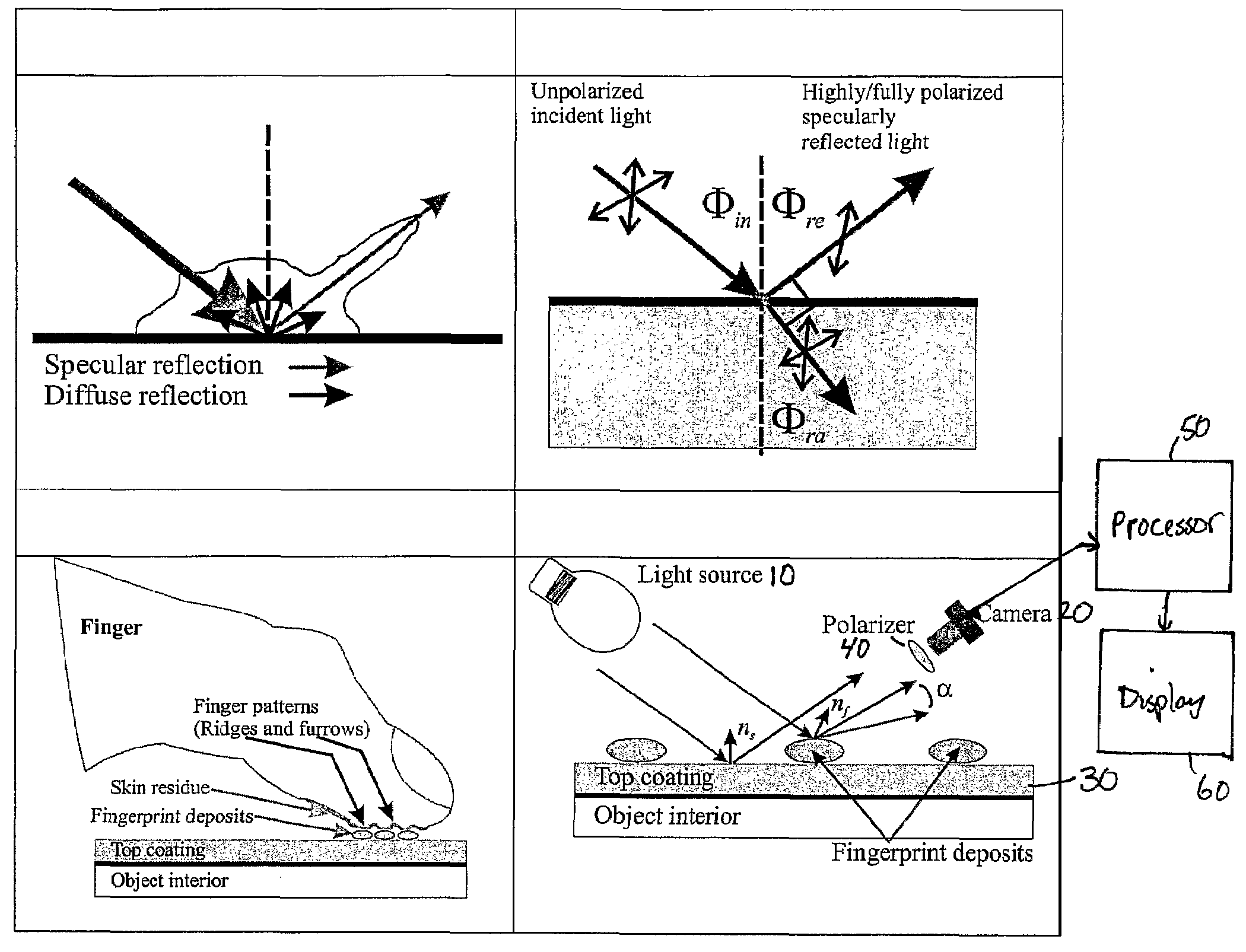
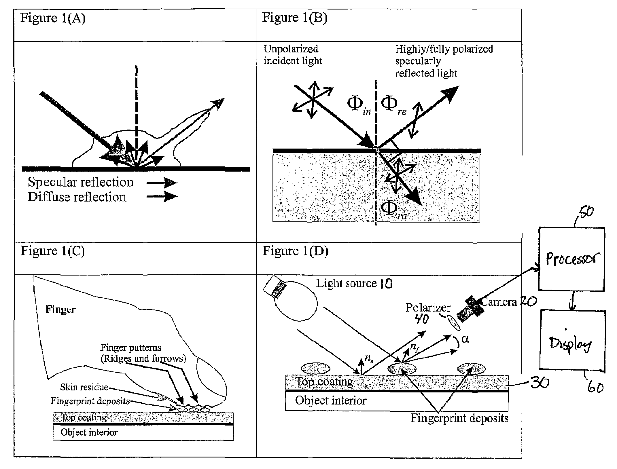
[0035]FIG. 1 illustrates the physical principles concerning non-contact latent fingerprint detection and extraction in accordance with the invention. FIG. 1(A) illu...


PUM


Abstract

An optical fingerprinting method extracts high quality latent fingerprints from a surface without any invasive chemical or physical contact with the examined object, and requires no cooperation of the subject. Rather than employing extraneous material, the optical properties of the latent fingerprint are used to generate one or more images with sufficient contrast to distinguish the latent fingerprint or some other deformation in the surface. The system includes a light source oriented to apply light at an angle of incidence to the surface at the position to be examined for the latent fingerprint or deformation, a camera oriented to receive light specularly and diffusely reflected from the surface and / or by the fingerprint or deformation on the surface, and a processor that performs the computation for digital contrast enhancement and / or reprojection of the recovered fingerprint image to a frontal view if necessary. The technique uses optical polarization properties to enhance the images by placing a linearly polarized filter(s) in front of the observing camera. At least two pictures of the same scene with the same lighting and view angle arrangement are taken whereby each of the pictures differ only in that the orientations of the polarization filter are different. At least two light polarization parameters for each pixel are computed from the two or more images taken with different polarizer orientations. An image with each pixel value representing the value of one of the polarization parameters or a function of the polarization parameters is generated and displayed, with some digital contrast enhancement and / or reprojection applied. The hidden latent fingerprint pattern is revealed in at least one such image with the interfering background pattern significantly suppressed.

Description

CROSS-REFERENCE TO RELATED APPLICATIONS[0001]This application is the National Stage of International Application No. PCT / US2005 / 014547, filed Apr. 27, 2005, which claims the benefit of the filing date of U.S. Provisional Application No. 60 / 565,669, filed Apr. 27, 2004, the disclosure of which is incorporated herein by reference in its entirety.GOVERNMENT INTEREST[0002]The present invention was supported in part by the U.S. Air Force Office of Scientific Research (AFOSR), through grants F49620-01-1-0470, F49620-02-1-0140, and the DURIP grant F49620-02-1-0241. The government may have certain rights in the invention.FIELD OF THE INVENTION[0003]The present invention relates to a method and apparatus for imaging and lifting fingerprints and, more particularly, to a method and apparatus for non-contact latent fingerprint imaging and lifting based on polarization and reflection differences in the visible band found between latent fingerprint marks and the underlying surfaces.BACKGROUND OF ...

Claims


Application Information

Patent Timeline
Patent Type & Authority Patents(United States)
IPC IPC(8): G06K9/74G06V10/60
CPCA61B5/1172A61B5/441G01N21/21G01N21/94G06K9/00013G06K9/00033G06K9/4661G06V40/1312G06V10/60
Inventor ENGHETA, NADERPUGH, JR., EDWARD N.LIN, SHIH-SCHONYEMELYANOV, KONSTANTIN MARIANOVICH
Owner THE TRUSTEES OF THE UNIV OF PENNSYLVANIA
Learn More