Pilot valve manifold

a pilot valve and manifold technology, applied in the direction of valve housings, fluid tightness measurement, instruments, etc., can solve the problems of large and cumbersome pneumatic systems, posing the potential for associated malfunction and leakage, and difficult to automate testing protocols

Inactive Publication Date: 2009-02-17
JOHNSON JOHN LESLIE +1
View PDF3 Cites 43 Cited by
  • Summary
  • Abstract
  • Description
  • Claims
  • Application Information

AI Technical Summary

Problems solved by technology

Nonetheless, the pneumatic system is expansive and cumbersome, with each element posing the potential for associated malfunction and leaks.
Further, automation of a testing protocol is difficult because of the independent relationship of the components.

Method used


Image

  • Pilot valve manifold
  • Pilot valve manifold
  • Pilot valve manifold

Examples


Embodiment Construction

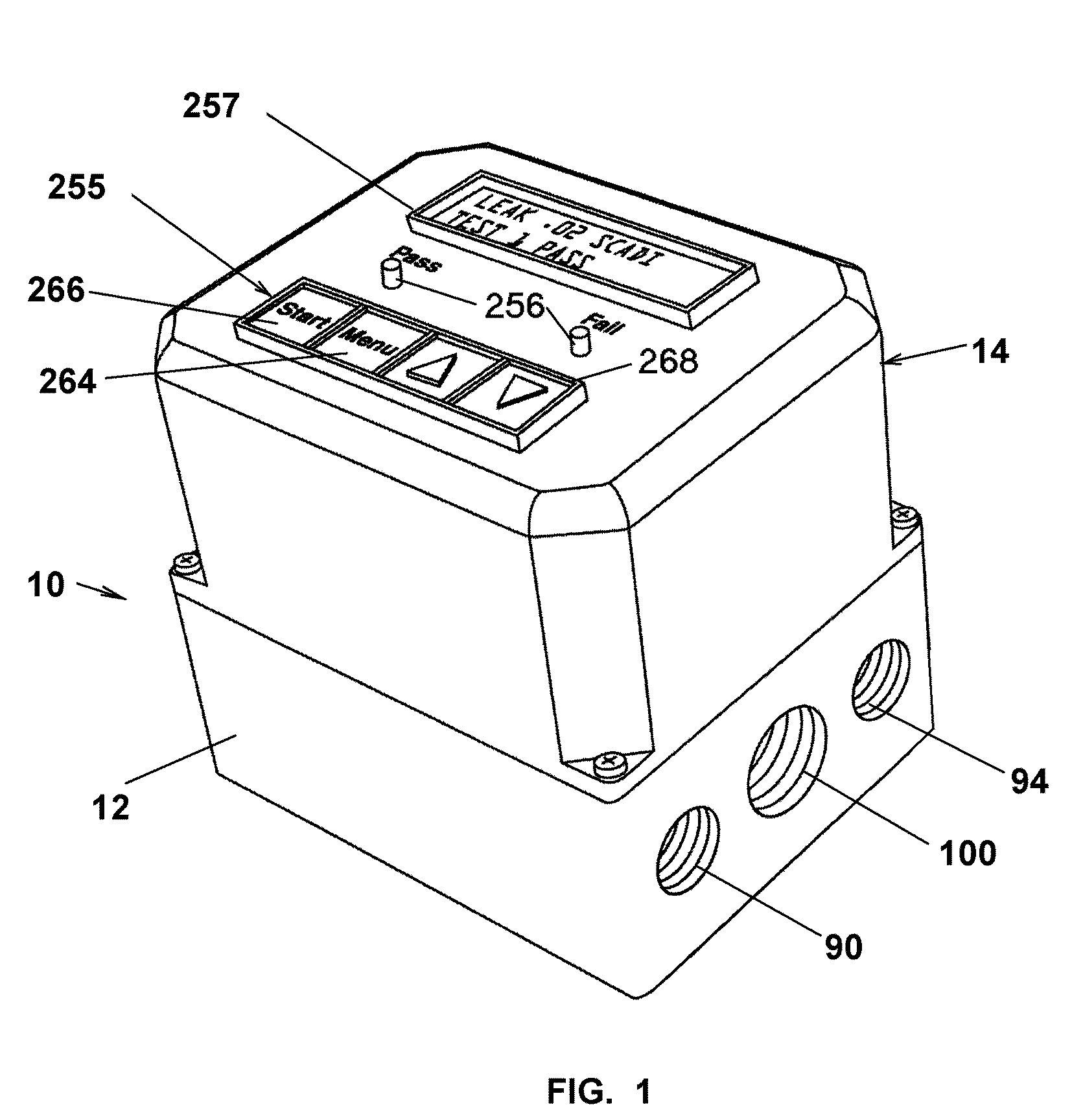
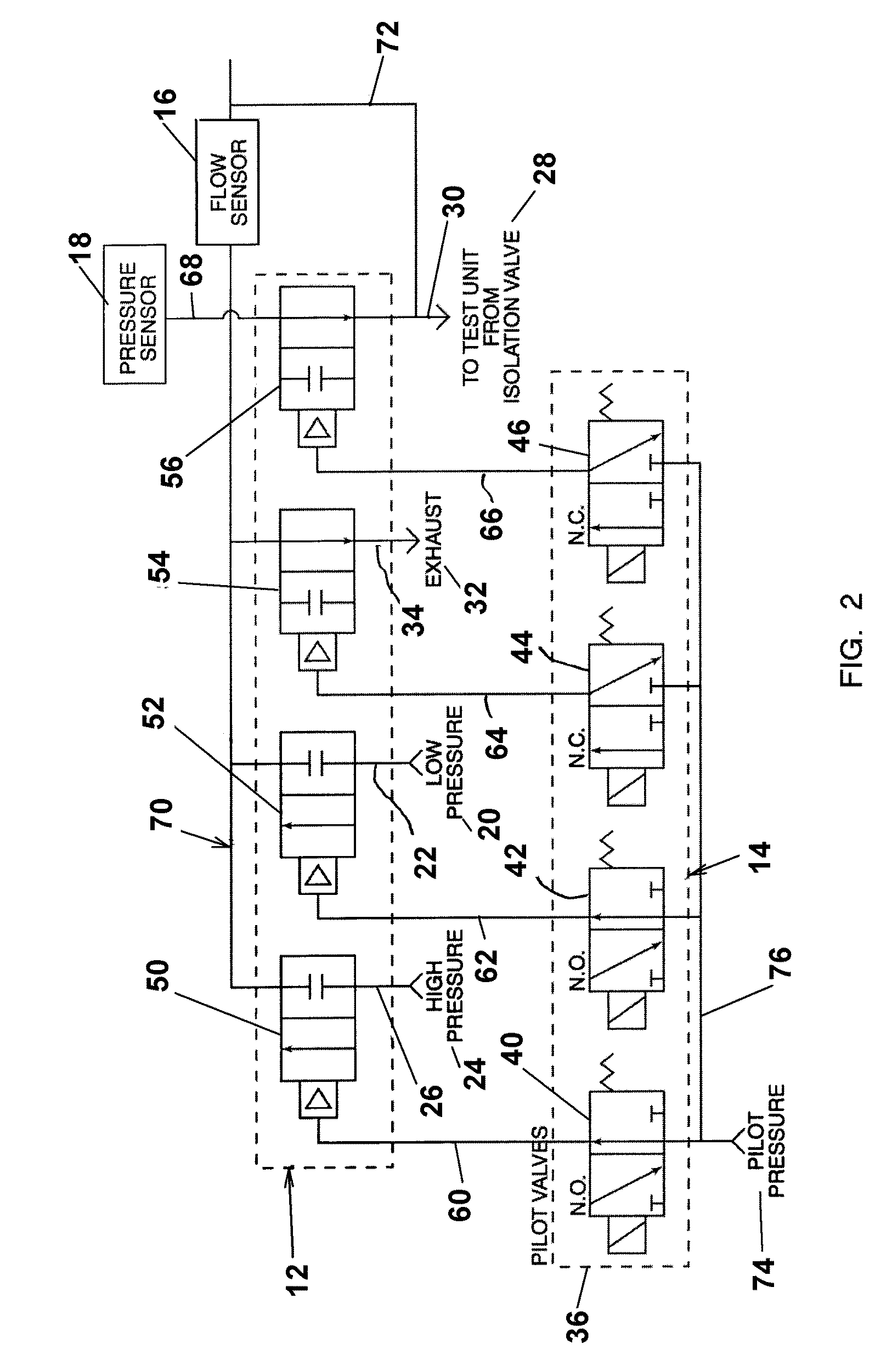
[0032]Referring to the drawings for the purpose of describing the preferred embodiment and not for limiting same, FIGS. 1 and 2 illustrate a leak detection system 10 for determining the pressure integrity of components when subjected to pressure conditions during a test period. The leak detection system 10 comprises a valve assembly 12 and a control module 14 operatively coupled with a flow sensor 16 and pressure sensor 18. As hereinafter described in detail, the leak detector 10 is operative for testing the fluid integrity of test parts to determine is leakage standards are being achieved.

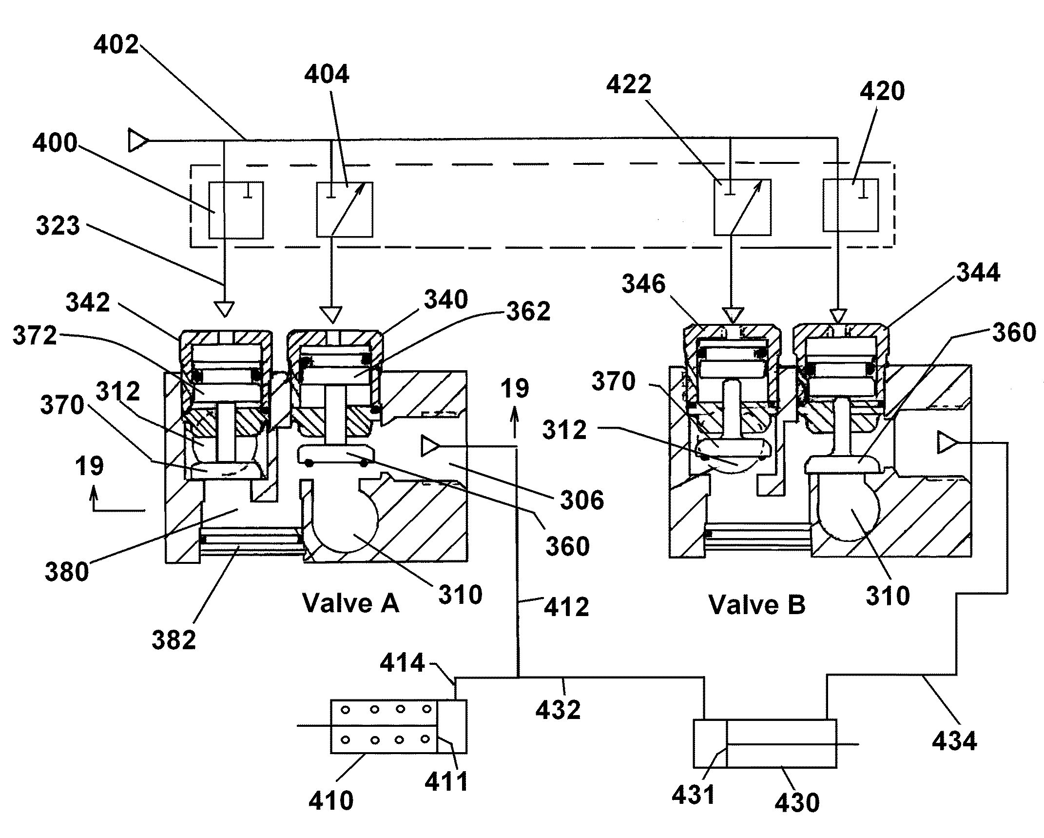
[0033]Referring additionally to FIG. 10, the valve assembly 12 is fluidly connected with a low pressure source 20 along line 22, a high pressure source 24 along line 26, a test unit 28 for testing such parts along line 30, and an exhaust 32 along line 34. Supplemental valves may be disposed in the lines for controlling flow therethrough.

[0034]The control module 14 comprises a pilot valve assembly ...


PUM


Abstract

A valve manifold includes a valve body carrying pairs of laterally spaced piston actuated valves controlled by control modules operative to selective pressurize and exhaust an outlet port connected to a fluidic device and configured in grouping permitting varying valve functionalities.

Description

RELATED APPLICATION[0001]This application is a continuation-in-part application of U.S. Ser. No. 09 / 840,688, filed on Apr. 23, 2001 now U.S. Pat. No. 6,435,010 in the names of Johnson et al. and entitled “Leak Detection System”.FIELD OF THE INVENTION[0002]The present invention relates to valves for controlling fluid flow, and, in particular, a control valve assembly having pitot valves integrated with a valve manifold for compactly controlling fluid coupled devices.BACKGROUND OF THE INVENTION[0003]Manufacturers of hydraulic, pneumatic, and containment equipment customarily test the fluid integrity of their components to ensure safe operation in the field. Standards are generally prescribed for leakage rates at test pressures and times correlated to the desired component specifications.[0004]Currently, leak detection systems are an assembly of separate components housed in portable test units. Using a myriad of valves and pneumatic lines a component to be tested is attached to the te...

Claims


Application Information

Patent Timeline
Patent Type & Authority Patents(United States)
IPC IPC(8): G01M3/04
CPCG01M3/3236F16K31/122Y10T137/87225Y10T137/87209Y10T137/87201F16K1/126F16K27/003F16K31/1225F16K37/0066F16K37/0091G01M3/2853G01M3/2876
Inventor JOHNSON, JOHN LESLIEJOHNSON, JAMES G.
Owner JOHNSON JOHN LESLIE
Why Eureka
Try Eureka