Selective coloring of a drawing surface to indicate a logical grouping

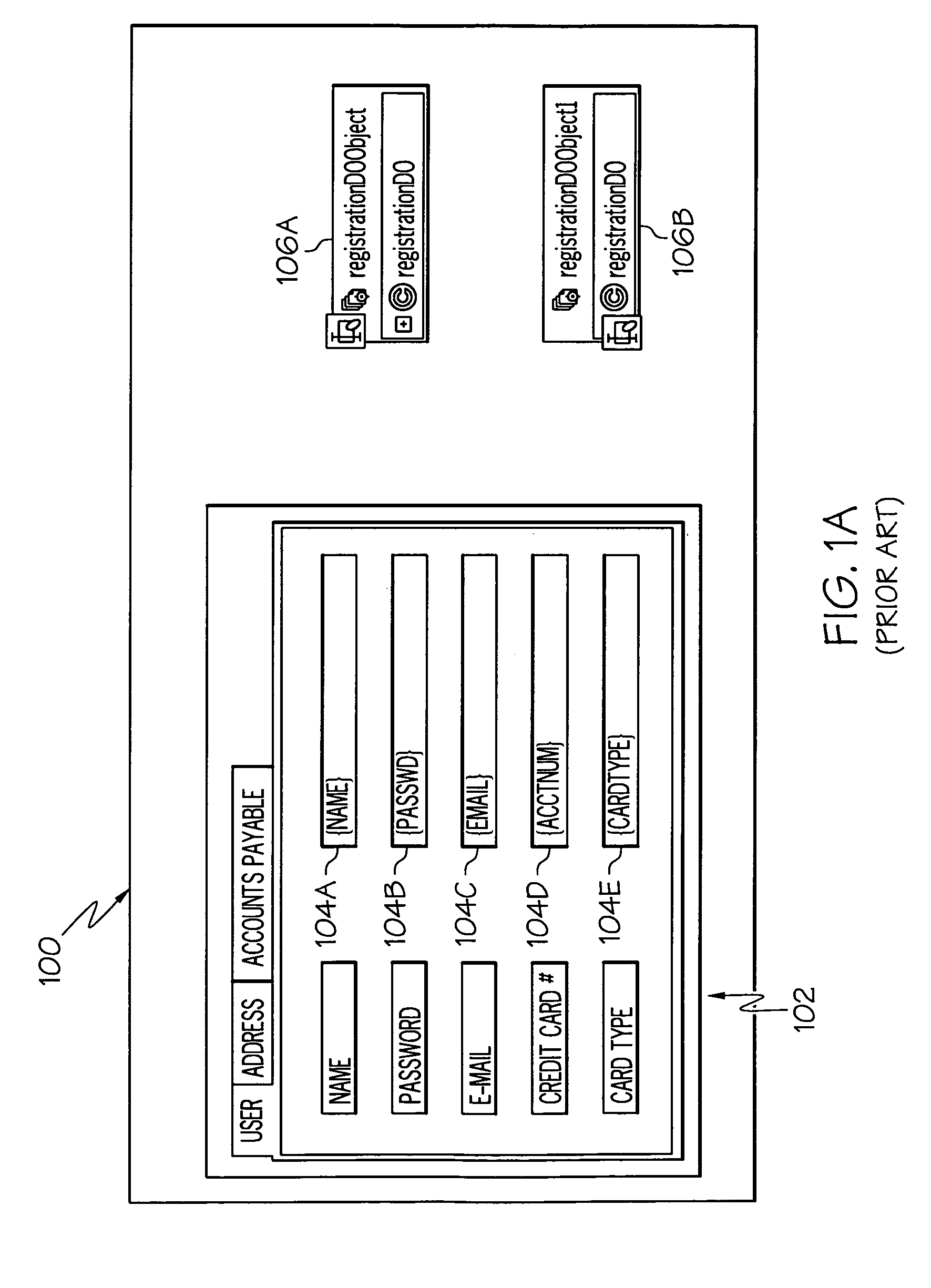
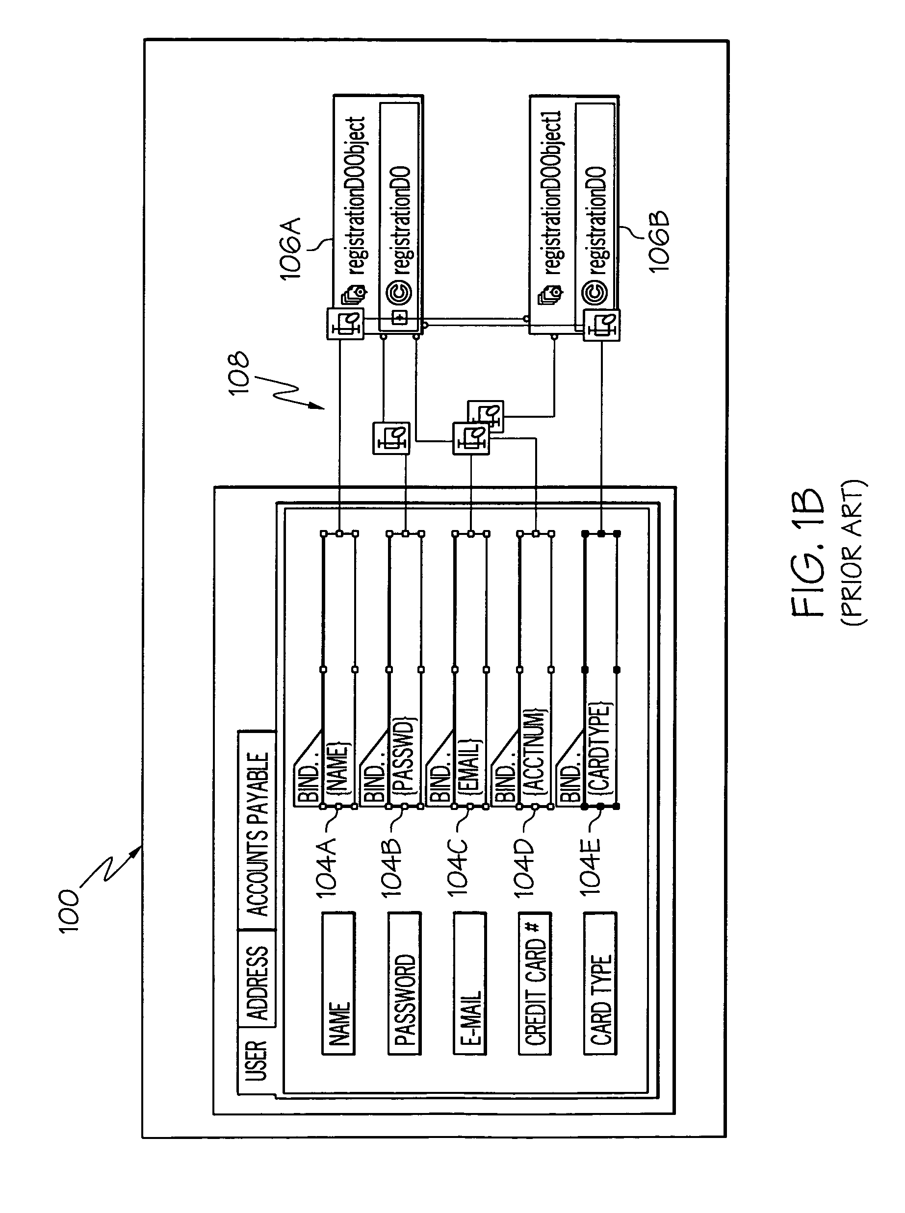
a drawing surface and logical grouping technology, applied in the computer field, can solve the problems of inability to move the location of text fields 104/b>, inadvertently changing the semantic meaning of the application, and the fig. 1/i>b/i> is not much better

Inactive Publication Date: 2009-02-24
INT BUSINESS MASCH CORP
View PDF9 Cites 4 Cited by
  • Summary
  • Abstract
  • Description
  • Claims
  • Application Information

AI Technical Summary

Benefits of technology

[0005]To address the problem described above regarding managing visual representations of relationships between active graphical areas such as text fields in a GUI and underlying software objects, an improved method, apparatus and computer-readable medium is presented. In one embodiment, the method includes the steps of receiving, by computer logic, a selection of an object graphical depiction of a data source software object, wherein the data source software object supports a field that is represented by a field graphical depiction in a Graphical User Interface (GUI); and in response to receiving the selection of the object graphical depiction, altering a physical appearance of the field graphical depiction, wherein altering the physical appearance of the field graphical depiction illustrates, in the GUI, a logical relationship between the data source software object and the field.

Problems solved by technology

While this written description of these relationships may be confusing and difficult to follow, FIG. 1b is not much better due to the numerous and cluttering lines 108.
Furthermore, arbitrarily moving lines 108, objects 106 and text field 104 just for the sake of visual uncluttering may lead to a problem of inadvertently changing the semantic meaning of the application.
Thus, the location of these text fields 104 cannot be moved merely to simplify the flow of the lines, as this would interfere with the desired runtime composition, which is the application's primary purpose.

Method used


Image

  • Selective coloring of a drawing surface to indicate a logical grouping
  • Selective coloring of a drawing surface to indicate a logical grouping
  • Selective coloring of a drawing surface to indicate a logical grouping

Examples


Embodiment Construction

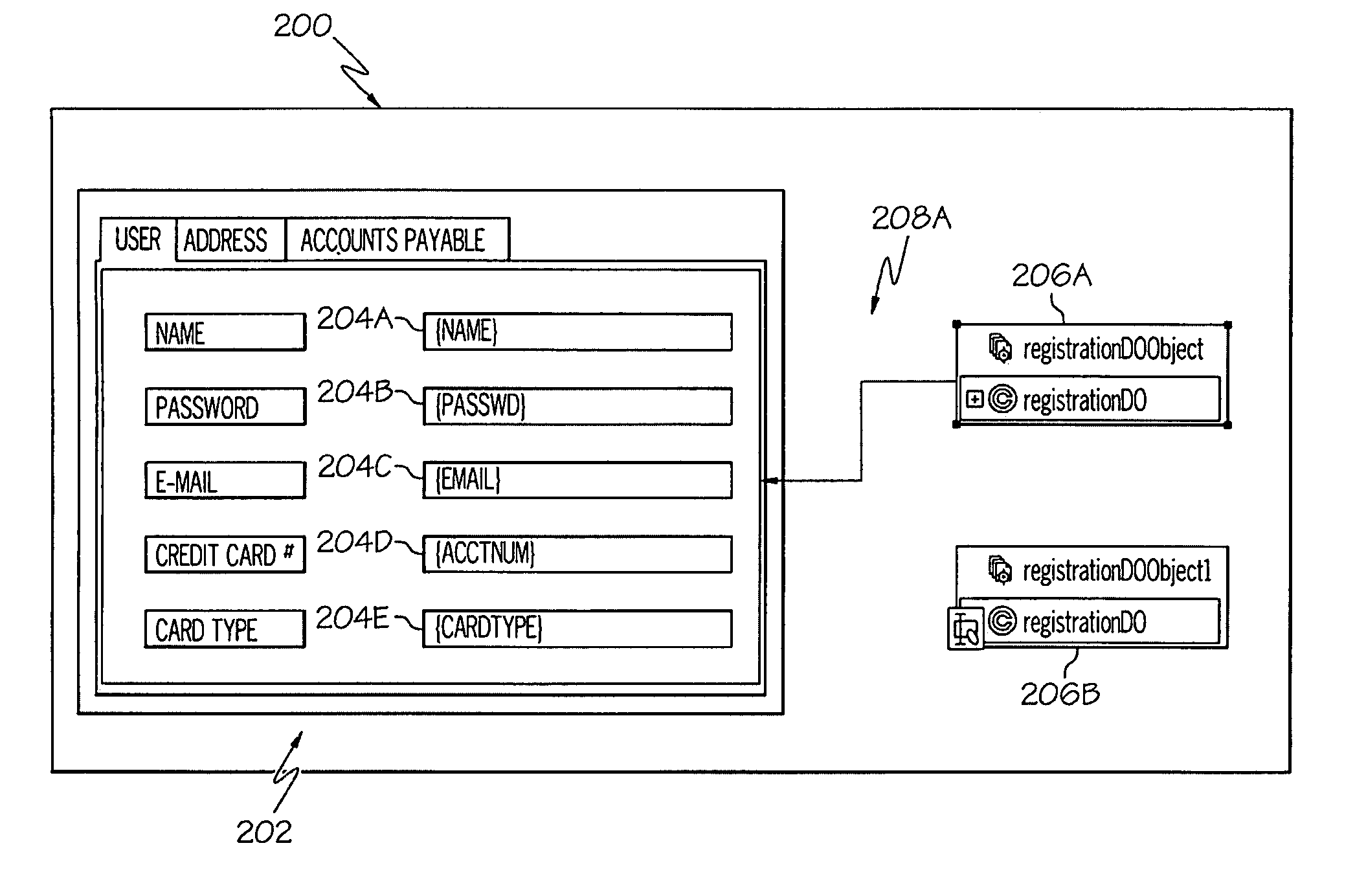
[0017]Referring now to FIG. 2a, a display 200 includes fields 204b, 204d, and 204e, which correspond with respective entry areas for “password”, “acctnum” and “cardtype,” and are left in their normal color when the representation for object, 206a is clicked. A line 208a shows which data source object 206a is the underlying object for these fields. At the same time, fields 204a and 204c become (or alternatively, remain) lightened (grayed out). This selective lightening of fields 204a and 204c is done when the data source object 206a is selected (e.g., by clicking the representation of data source object 206a, or by selecting data source object 206a from a drop-down menu (not, shown). This allows the user to choose a figure and see what underlying object is associated with it and not have a large number of lines drawn which encounter the problems described earlier. Additionally, clicking or otherwise selecting, one of the fields 204 will result in a line 208 being automatically drawn ...


PUM


Abstract

A method, apparatus and computer-readable medium for managing visual representations of relationships between active graphical areas such as text fields in a GUI and underlying software objects is presented. In one embodiment, the method includes the steps of receiving, by computer logic, a selection of an object graphical depiction of a data source software object, wherein the data source software object supports a field that is represented by a field graphical depiction in a Graphical User Interface (GUI); and in response to receiving the selection of the object graphical depiction, altering a physical appearance of the field graphical depiction, wherein altering the physical appearance of the field graphical depiction illustrates, in the GUI, a logical relationship between the data source software object and the field.

Description

BACKGROUND OF THE INVENTION[0001]The present invention relates in general to the field of computers and similar technologies, and in particular to software utilized in this field.[0002]Graphical User Interfaces (GUIs) can use drawing surfaces to render information to the user. This information may itself be part of an underlying model of data, such as a set of nodes and arcs, or the information may be a software tool that uses shapes to show a runtime representation of a data model of underlying objects. For example, a display 100, shown in FIG. 1a, depicts a deployed FIG. 102 (which includes a text field 104a for inputting “name” data, a text field 104b for inputting “password” data, a text field 104c for inputting “email” name data, etc.) and underlying software objects 106a-b. Logical relationships exist between text fields 104a-e and specific software objects 106a-b. Part of the application's usage might involve illustrating a set of such relationships to the user.[0003]One way ...

Claims


Application Information

Patent Timeline
Patent Type & Authority Patents(United States)
IPC IPC(8): G06F3/048G06F3/00G06F17/00G06F7/00
CPCG06F3/0481G06F3/04817G06F3/0482G06F9/4443G06F9/451Y10S707/99943
Inventor MENDEL, GILIWINCHESTER, JOSEPH R.
Owner INT BUSINESS MASCH CORP
Why Eureka
Try Eureka