Gas-blast circuit breaker

a circuit breaker and gas blast technology, applied in the direction of air breakers, contact mechanisms, high-tension/heavy-dress switches, etc., can solve problems such as troublesome mounting work, and achieve the effect of sufficient insulation distance and easy operation

Inactive Publication Date: 2009-03-03
MITSUBISHI ELECTRIC CORP
View PDF9 Cites 3 Cited by
  • Summary
  • Abstract
  • Description
  • Claims
  • Application Information

AI Technical Summary

Benefits of technology

[0006]The invention is directed to obtaining a gas-blast circuit breaker, which can ensure a sufficient insulation distance and appropriately and easily perform working of and a mount work of an insulating member.
[0008]According to the invention, it is possible to obtain a gas-blast circuit breaker, which can ensure a sufficient insulation distance and appropriately and easily perform working of and a mount work of mount portions of an insulating member.

Problems solved by technology

Such related art involves a problem that the boss member protrusively provided in the inside of the ground tank makes it impossible to ensure a sufficient insulation distance, working of a mount surface of the boss member to which the insulating member is mounted is difficult, and a mount work becomes troublesome.

Method used


Image

  • Gas-blast circuit breaker
  • Gas-blast circuit breaker
  • Gas-blast circuit breaker

Examples


embodiment 1

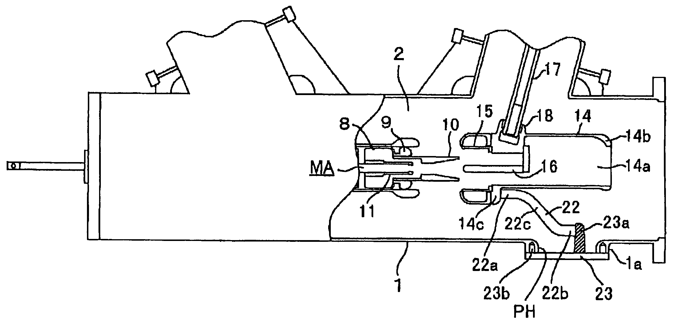
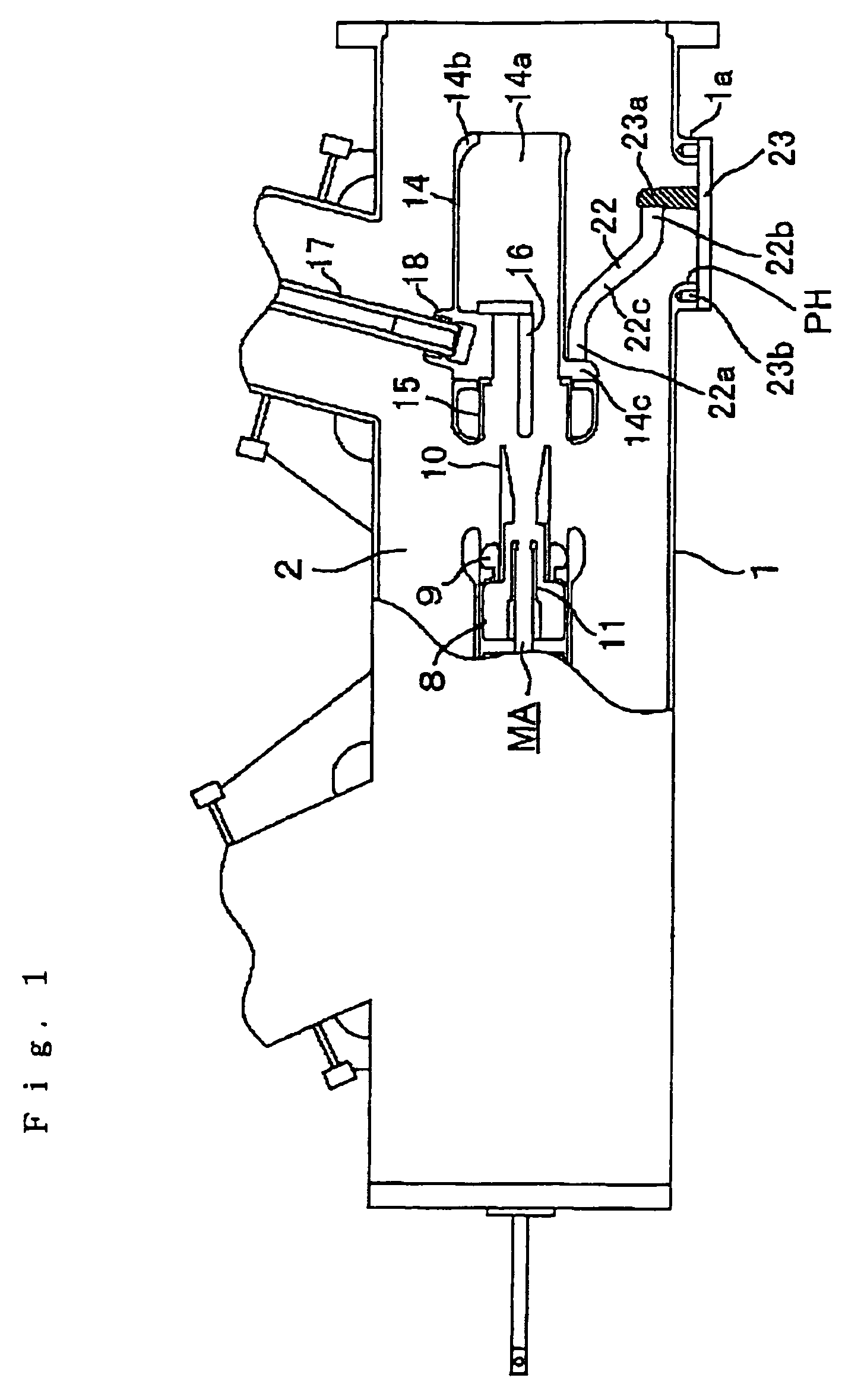
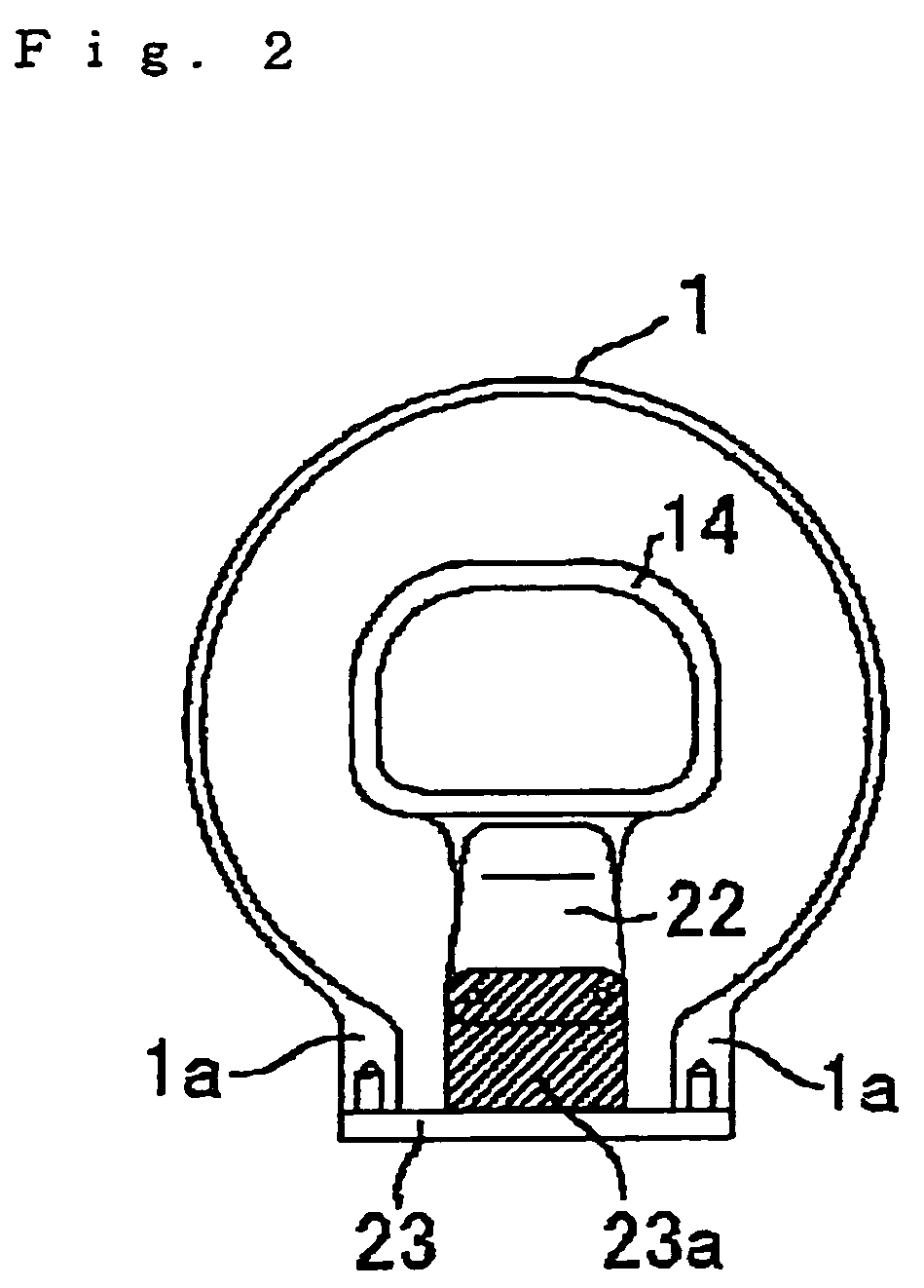
[0011]Embodiment 1 of the invention will be described with reference to the drawings. FIG. 1 is a side view showing the construction of the embodiment according to the invention. FIG. 2 is a transverse, cross sectional view showing the construction of the embodiment according to the invention.

[0012]In FIGS. 1 and 2 showing the construction of the embodiment according to the invention, insulating gases 2 such as SF6 gases or the like are charged in a ground metal tank 1 kept at earth potential.

[0013]An inside diameter portion of a puffer cylinder 8, which is driven horizontally as shown in FIG. 1, contacts slidably with an outer periphery of a piston (not shown), the puffer cylinder 8 forming a current-carrying conductive path.

[0014]A cylindrical-shaped moving contact 9 is mounted to a tip end of the puffer cylinder 8. A cylindrical-shaped insulating nozzle 10 is provided on an inner peripheral side of the moving contact 9 with an interior thereof communicated to an interior of the p...


PUM


Abstract

The gas-blast circuit breaker includes an electrically conductive vessel charged with insulating gases and kept at earth potential, a stationary arc-extinguishing chamber accommodated in a ground metal tank and corresponding to a moving part to extinguish an arc generated between it and the moving part, an insulating member that supports the stationary arc-extinguishing chamber to insulate the same from an earth potential portion, an opening provided on the ground metal tank, and a lid body that closes the opening provided on the ground metal tank and is arranged detachably on the opening from outside the ground metal tank, and one end of the insulating member is mounted to a mount provided on the lid body, and therefore a gas-blast circuit breaker is obtained to enable ensuring a sufficient insulation distance and appropriately and easily performing working of and a mount work of mount portions of an insulating member.

Description

BACKGROUND OF THE INVENTION[0001]1. Field of the Invention[0002]The present invention relates to a gas-blast circuit breaker, and more particular, to a gas-blast circuit breaker, in which a stationary arc-extinguishing chamber is supported through an insulator on a ground.[0003]2. Description of the Related Art[0004]In a gas-blast circuit breaker, in which a stationary arc-extinguishing chamber is supported through an insulating member on a ground, the insulating member, which insulatingly supports the stationary arc-extinguishing chamber, according to the related art is mounted to a boss member protrusively provided in a ground tank to be made integral therewith (for example, see JP-A-6-96644).[0005]Such related art involves a problem that the boss member protrusively provided in the inside of the ground tank makes it impossible to ensure a sufficient insulation distance, working of a mount surface of the boss member to which the insulating member is mounted is difficult, and a mou...

Claims


Application Information

Patent Timeline
Patent Type & Authority Patents(United States)
IPC IPC(8): H01H33/70
CPCH01H33/53
Inventor YOSHITOMO, YUJI
Owner MITSUBISHI ELECTRIC CORP
Why Eureka
Try Eureka