
A cable terminal connecting device for gis and gis

A technology of cable terminals and connecting devices, which is applied in the field of cable terminal connecting devices for GIS, can solve problems such as SF6 gas waste, achieve the effects of reducing labor intensity, avoiding discharge phenomena, improving work efficiency and product reliability

Active Publication Date: 2022-08-09
PINGGAO GRP +2
View PDF5 Cites 0 Cited by
  • Summary
  • Abstract
  • Description
  • Claims
  • Application Information

AI Technical Summary

Problems solved by technology

[0005] The purpose of the present invention is to provide a cable terminal connection device for GIS to solve the problem of wasting SF6 gas due to the need to repeatedly charge and discharge SF6 gas into the cylinder when carrying out withstand voltage tests on the GIS body and the power cable in the prior art The technical problem; The purpose of the present invention is also to provide a kind of GIS

Method used


Image

  • A cable terminal connecting device for gis and gis
  • A cable terminal connecting device for gis and gis
  • A cable terminal connecting device for gis and gis

Examples


Embodiment 1

[0067] like Figure 4 As shown, the GIS includes a GIS body 21 and a cable terminal connecting device, and the cable terminal connecting device is used to connect the power cable and the GIS body 21 . Among them, GIS ontology is an existing mature product, which will not be repeated here.

[0068] like Figure 4 and Figure 5 As shown, the cable terminal connection device includes a cylinder body 22, the cylinder body 22 extends in the vertical direction, the cylinder body 22 is provided with a cable terminal 23, the lower end of the cable terminal 23 is used for connecting the power cable, and the upper end of the cable terminal 23 is fixed with The first static contact 24 .

[0069] In this embodiment, the cylinder body 22 has a first cylinder opening and a second cylinder opening, the first cylinder opening is arranged to the right, the first cylinder opening is butted with the GIS body 21, and a first insulator 30 is fixed between the first cylinder opening and the GIS ...

Embodiment 2

[0083] The difference between this embodiment and Embodiment 1 is that in Embodiment 1, the cylinder 22 includes a cylinder body and a transition cylinder 31 , one end of the transition cylinder 31 is connected to the cylinder body through a flange structure, and the other end of the transition cylinder 31 is connected to the cylinder body. The second barrel opening is formed, and the end cap 28 is fixedly connected to the transition barrel 31 . In this embodiment, the cylinder body is not provided with a transition cylinder, and the end cap is directly fixed to the cylinder body. During the pressure test, after removing the end cap, first install the transition cylinder on the cylinder body, and then install the pressure resistant sleeve. .

Embodiment 3

[0085] The difference between this embodiment and Embodiment 1 is that, in Embodiment 1, the second insulator 27 is a basin-type insulator. In this embodiment, the second insulator is a flat insulator.


PUM


Abstract

The invention relates to a cable terminal connecting device for GIS and a GIS. The cable terminal connection device for GIS includes: a cylinder body, which is provided with a cable terminal, a first static contact is electrically connected to the cable terminal, the cylinder body has a first cylinder opening and a second cylinder opening; an end cap is fixed on the second cylinder On the barrel mouth, it is used to block the second barrel mouth, and the end cap is removed during the withstand voltage test; the first insulator is fixed at the first barrel mouth, and the inner side of the insert is fixed with a second static contact, the second The static contact is used for conductive connection with the GIS body; the edge of the second insulator is fixed between the second barrel opening and the end cap, and the inner side of the insert on the second insulator is fixed with a contact seat; the moving contact is hinged on the On the contact seat, the moving contact has three working positions during the swinging process. In the first working position, the moving contact and the first static contact conduct conduction, and in the second working position, the moving contact and the first and second The two static contacts are both conducting, and the moving contact is conducting with the second static contact when in the third working position.

Description

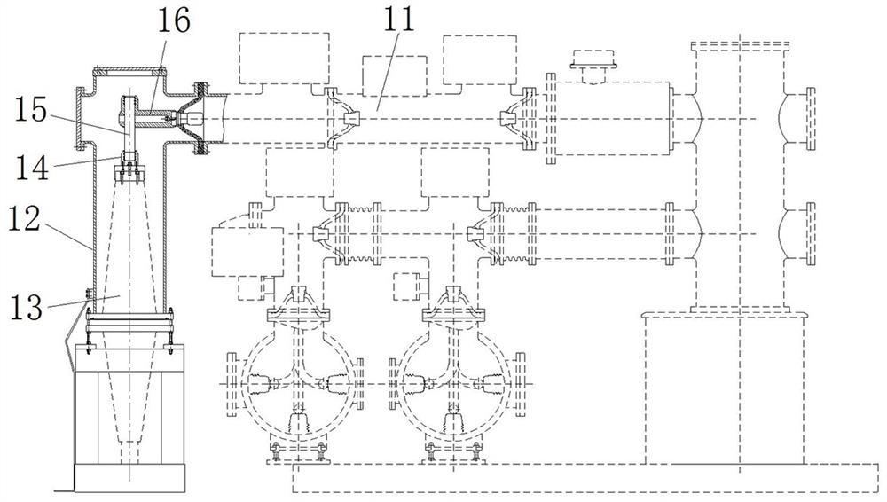
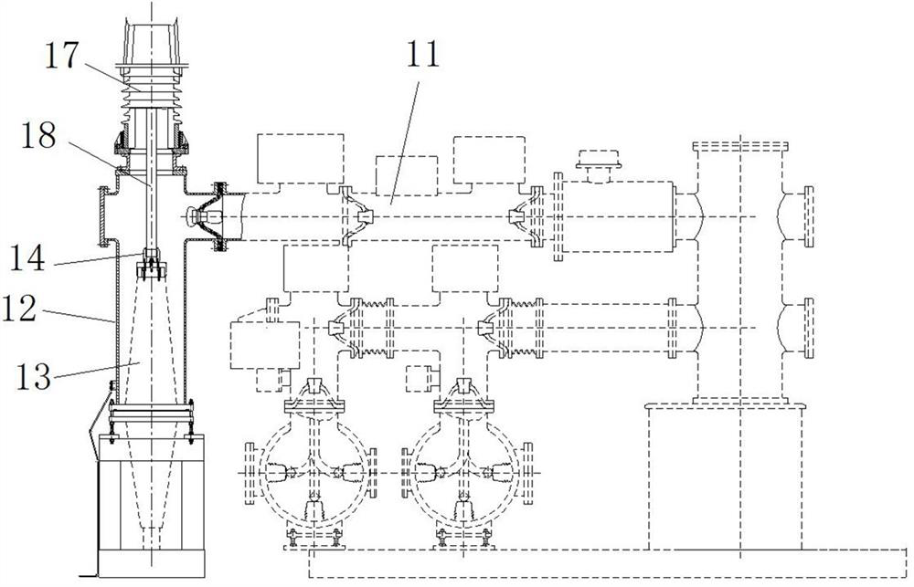
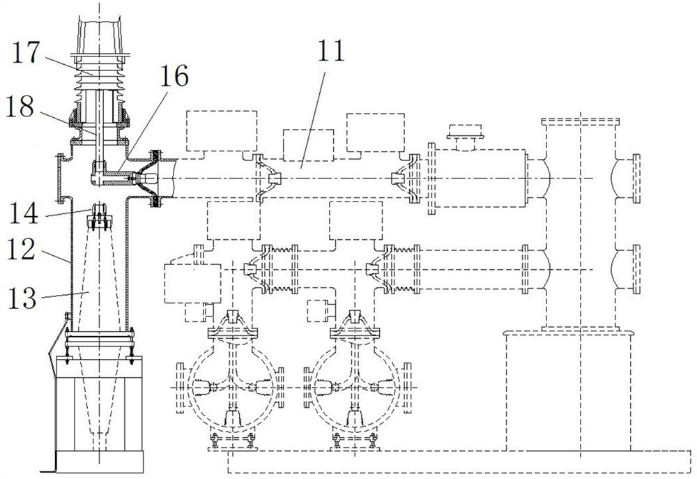
technical field [0001] The invention relates to a cable terminal connecting device for GIS and a GIS. Background technique [0002] The cable terminal connection device for GIS is a necessary device to connect the power cable and the GIS body. Since the on-site withstand voltage test parameters of the GIS body and the power cable are inconsistent, it is necessary to carry out the withstand voltage test independently for the two. [0003] At present, the existing GIS cable terminal connection devices such as figure 1 As shown, it includes a cylinder body 12, a cable terminal 13 is arranged in the cylinder body 12, the lower end of the cable terminal 13 is connected to the power cable, the upper end of the cable terminal 13 is fixed with a cable terminal contact 14, and the cable terminal contact 14 is connected through the first connection The conductor 15 and the second connecting conductor 16 are electrically connected to the GIS body 11 . When the power cable is subjecte...

Claims


Application Information

Patent Timeline
Patent Type & Authority Patents(China)
IPC IPC(8): H02G15/06H02G15/04H02G15/068H02B13/035H02B13/065
CPCH02G15/06H02G15/043H02G15/068H02B13/0358H02B13/065
Inventor 李忠富闫亚刚孙鹏王大伟吴军辉杨卫国陈富国赵献臣蔡杰李中旗王光磊张自华张娟张猛超
Owner PINGGAO GRP
Learn More