Video display and touchscreen assembly, system and method

a touchscreen and video display technology, applied in the field of assembly, can solve the problems of increasing the failure rate of consoles generally, adding steps and costs to the manufacturing process, and not uncommonly affecting the frontal impact of consoles by users

Active Publication Date: 2009-03-03
WELLS GARDNER TECH INC
View PDF9 Cites 161 Cited by
  • Summary
  • Abstract
  • Description
  • Claims
  • Application Information

AI Technical Summary

Problems solved by technology

Such consoles are thus not uncommonly subjected to violent frontal impacts from users, such as by the user's fist or a wielded item.
External buttons and sensors have the disadvantage of having to be individually installed in a console and connected to the console's electronics, which adds steps and expense to the manufacturing process.
Such buttons and sensors also have the disadvantage of being susceptible to damage from users and the environment, and thus contribute to higher failure rates of the console generally.
The potential for damage to such buttons and sensors is more acute where the console is installed in a remote location where console users are not continually supervised.
Flat panel displays, however, and especially LCD screens, are damaged by contact or impact more easily than CRT displays.
The touch sensor itself, however, is not well suited to protect a flat panel display from damage, particularly from a frontal impact, as it is generally constructed of thin, flexible plastic sheet with associated electronics.
Thus, force from a frontal impact is readily transmitted through the touch screen to the flat panel display, thereby allowing the flat panel display to be relatively easily damaged.
Another problem with this type of assembly becomes evident in the event that the flat panel display becomes non-operational.
In such a case, the entire assembly must be discarded because the touch screen and flat panel display are not easily separated without damaging the flat panel display screen.
This method is not without problems, however.
Tempered glass is expensive and must be cut to size, thereby increasing both materials and labor costs.
In addition, tempered glass, while stronger than non-tempered glass, is still fragile and requires special handling during manufacture, installation, and use.
And when installed, frontal impact may cause the tempered glass to shatter, and thus damage the display over which the tempered glass and touch screen were mounted.
Another disadvantage to this assembly is the propensity for the touch screen to delaminate from the tempered glass, especially when the assembly is subjected to wide ranges of temperature and atmospheric conditions.

Method used


Image

  • Video display and touchscreen assembly, system and method
  • Video display and touchscreen assembly, system and method
  • Video display and touchscreen assembly, system and method

Examples


Embodiment Construction

[0029]While the present invention, in one embodiment, is particularly well suited for use with an LCD screen as will be explained herein, the devices and methods described may be used with other display apparatuses with similar benefits.

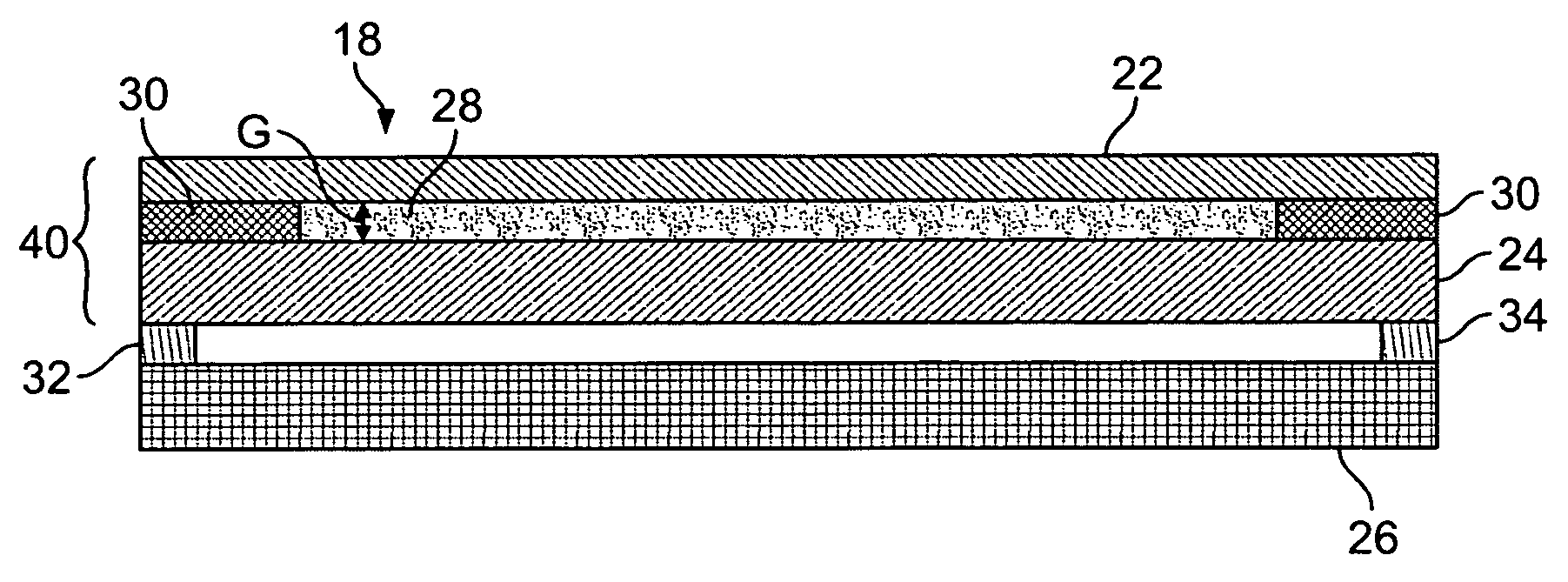
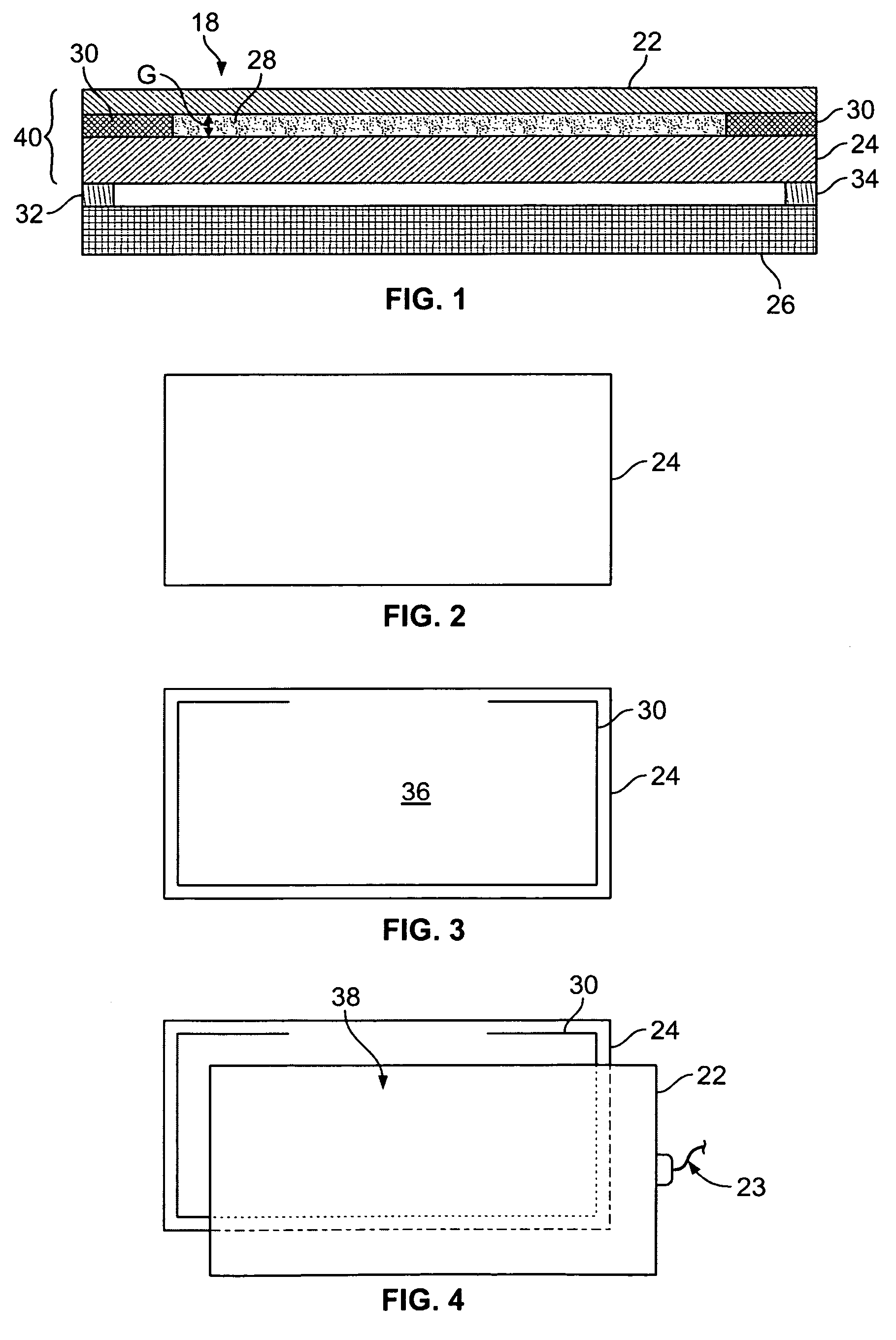
[0030]FIG. 1 shows a combined display and unitary touch screen assembly 18 (not to scale) according to one embodiment of the invention. Generally, the combined display and unitary touch screen assembly 18 includes a planar touch screen device 22 that is contactable by the user. The touch screen device 22 is connected to and spaced a distance G from a panel of transparent material 24 to form a gap therebetween. A display 26, such as an LCD display or the like, may be connected to and spaced from the panel of transparent panel 24. In other embodiments, the display 26 and the transparent panel 24, which is further incorporated into a unitary touch screen assembly as explained below, are not connected but are mounted or otherwise maintained in a prescrib...


PUM

PropertyMeasurementUnit
transparentaaaaaaaaaa
modulus of elasticityaaaaaaaaaa
resilientaaaaaaaaaa

Abstract

A touch screen assembly for use with a display, such as a flat panel display. The touch screen assembly includes a transparent panel, preferably in the form of a panel of tempered glass adhered to a touch screen panel. Consoles having touch screen assemblies are also disclosed.

Description

[0001]This application claims the benefit of U.S. Provisional Application No. 60 / 666,292, filed Mar. 29, 2005.FIELD OF THE INVENTION[0002]The subject invention relates to assemblies including video display and touch sensitive screen elements. More particularly, the invention relates to a system and method for combining a flat panel display, such as, for example, a liquid crystal display (LCD) screen, with a touch sensitive device and products made thereby.BACKGROUND OF THE INVENTION[0003]Video displays are ubiquitous features in homes, businesses, and public places, and are primarily used to provide a visual presentation generated by, for example, personal computers, electronic kiosks, video games, PDAs, cellular phones, and the like. Until relatively recently, most large video displays have been of the cathode ray tube (“CRT”) type, which employs an elongated glass vacuum tube wherein the length of the tube is proportional to the surface area of the display screen. CRT displays are...

Claims


Application Information

Patent Timeline
Patent Type & Authority Patents(United States)
IPC IPC(8): G06F3/041
CPCG06F1/1607G06F3/041
Inventor LUBE, ROBERT R.
Owner WELLS GARDNER TECH INC
Why Eureka
Try Eureka